83
APPENDIX C. FUSE REPLACEMENT
In the event that the controller fails to power up when the power switch is turned on, check
the line power fuse to see if it has blown. The fuse is located in the fuse holder on the power
entry module on the back of the controller. To remove the fuse holder first unplug the power
cord from the power entry module. This will reveal a slot just under the edge of the fuse
holder. Use a screwdriver to pry the holder straight out of the power entry module.
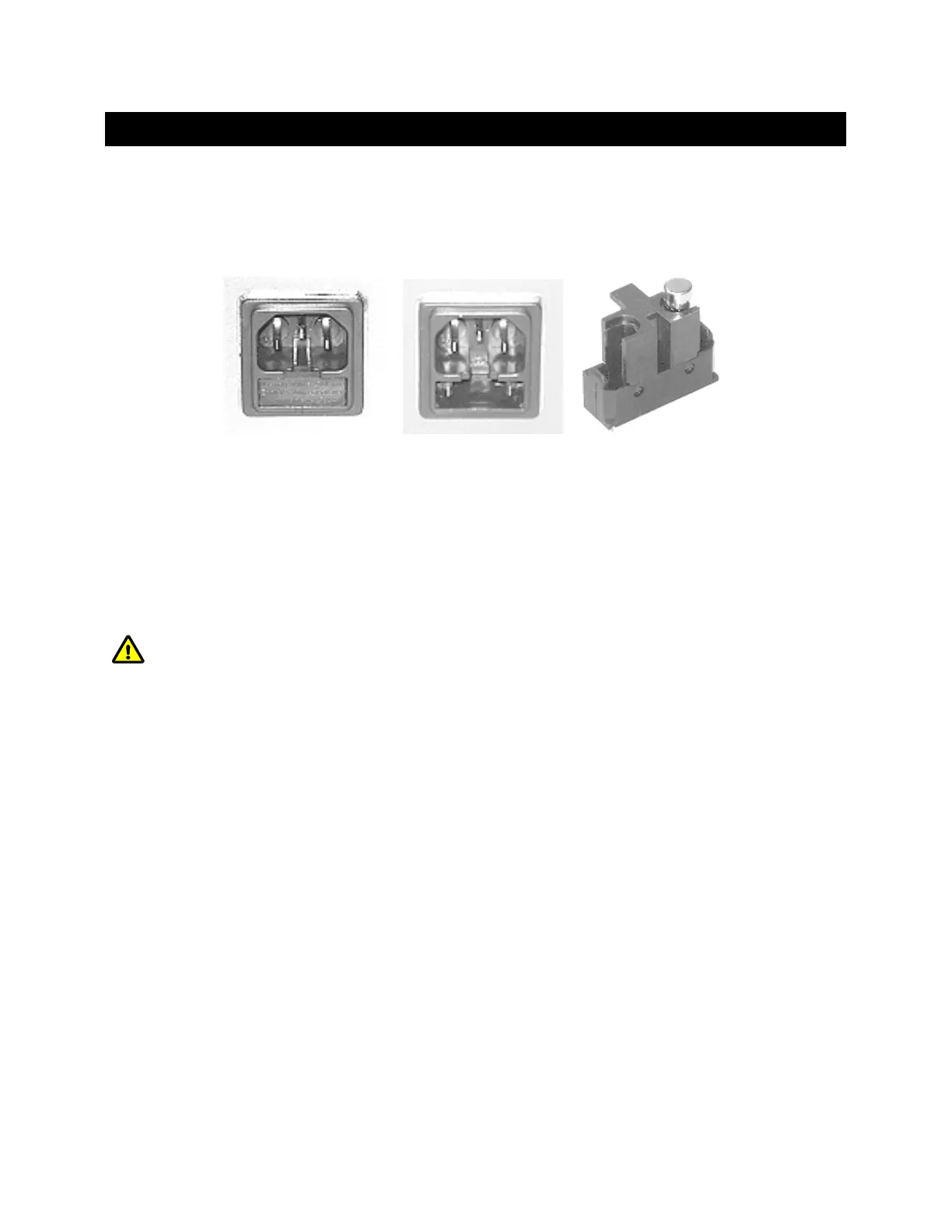
Power entry module. Fuse holder removed Fuse holder (spare fuse
not shown)
Figure 6-10. Power entry module and fuse holder.
The fuse that is readily visible in the fuse holder when you take it out is the one that is
“active” when the holder is installed. A spare fuse is also stored within the fuse holder.
Replace the active fuse with the spare and re-install the fuse holder and power cord. If the
controller fails to power up with the new fuse installed, call Sutter Instrument technical
support personnel for assistance.
Replace fuse only with the same type and rating:
Type: Medium Time Delay (or Time Lag), 5 x 20 mm glass tube, IEC 60127-2, RoHS
compliant.
Rating: T4A 250V (Time Delay, 4 Amps, 250 Volts)
Examples: Bussmann S506-4-R or Littelfuse 218 004.P (or 218 004.HXP)
P-1000 FLAMING/BROWN MICROPIPETTE PULLER SYSTEM OPERATION MANUAL – REV. 3.02 (20161118)