77
CAUTION: Never clamp a piece of glass to test a Pull. Something may get broken as a
result.
Press PULL to run the test. The End of Puller bar travel sensor shows “Tripped”
when the bars are apart, not when they are fully together.
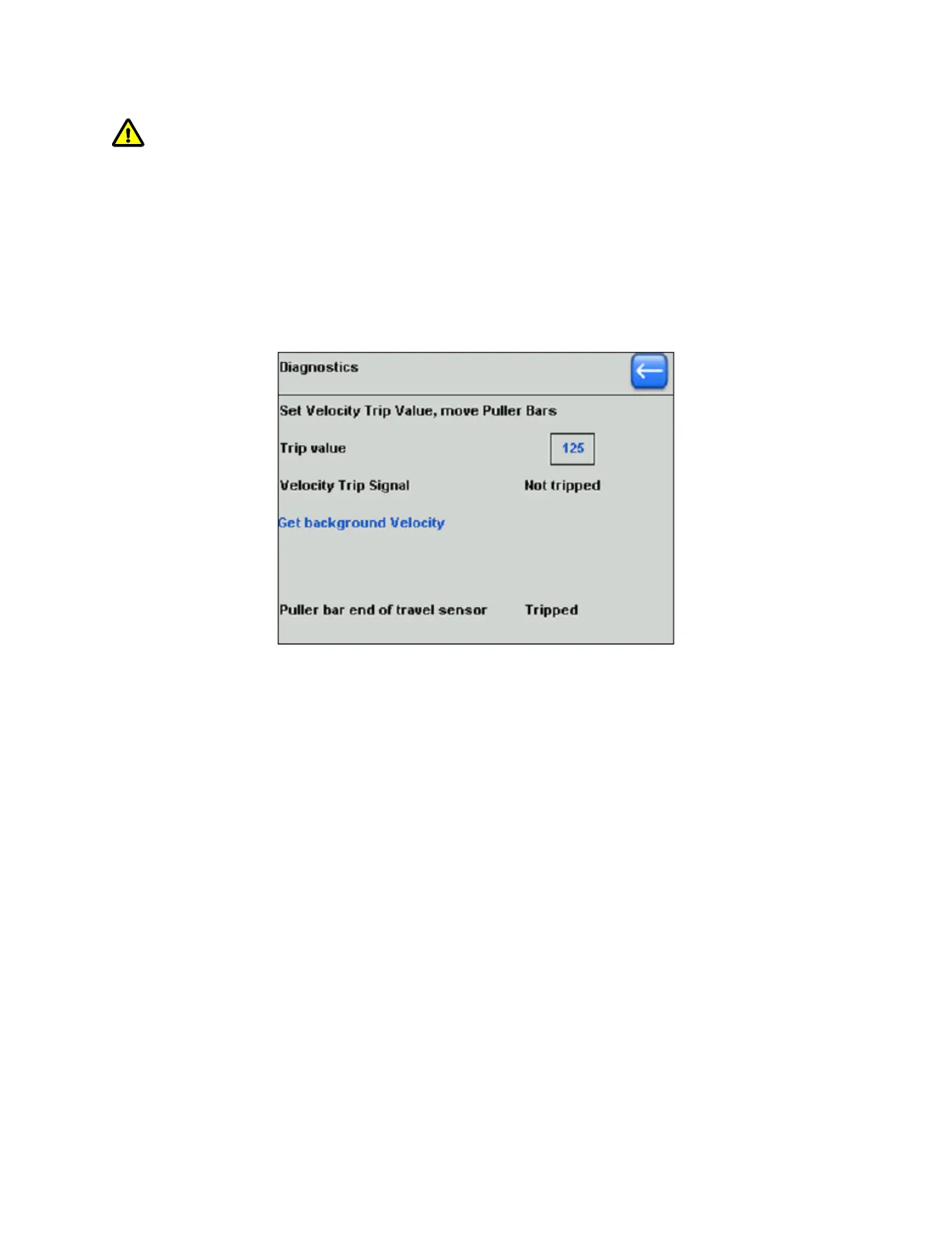
6.3.4 Velocity Diagnostics
The velocity diagnostics screen is reached by pressing “Velocity” in the main
diagnostics screen. The Velocity diagnostics screen is shown in the following figure.
Figure 6-7. Velocity diagnostics screen.
In this screen, you can check the sensitivity of the velocity sensor and the operation
of the optical sensor that detects when the glass has separated.
The Velocity value is always highlighted for editing with the Dial. Press ENTER to
set.
When the Puller Bars move apart, a signal is generated that is dependent on the
velocity of separation.
The Velocity setting is the threshold value at which the Trip occurs, as indicated on
the screen.
A difference in sensitivity to movement at higher or lower settings can be noticed.
The Background Velocity serves to calibrate the true zero reading. It is typically 1-2
units. A higher number can indicate an electronic fault.
This calibration is done automatically at each pull.
The “Puller bar end of travel sensor” shows “Tripped” when the bars are apart and
“Not Tripped” when they are fully together.
Adjust your Program Heat values to reflect the change in Ramp value.
P-1000 FLAMING/BROWN MICROPIPETTE PULLER SYSTEM OPERATION MANUAL – REV. 3.02 (20161118)