to the settings should not be performed without the supervision of Sutter Instrument
Technical Support.
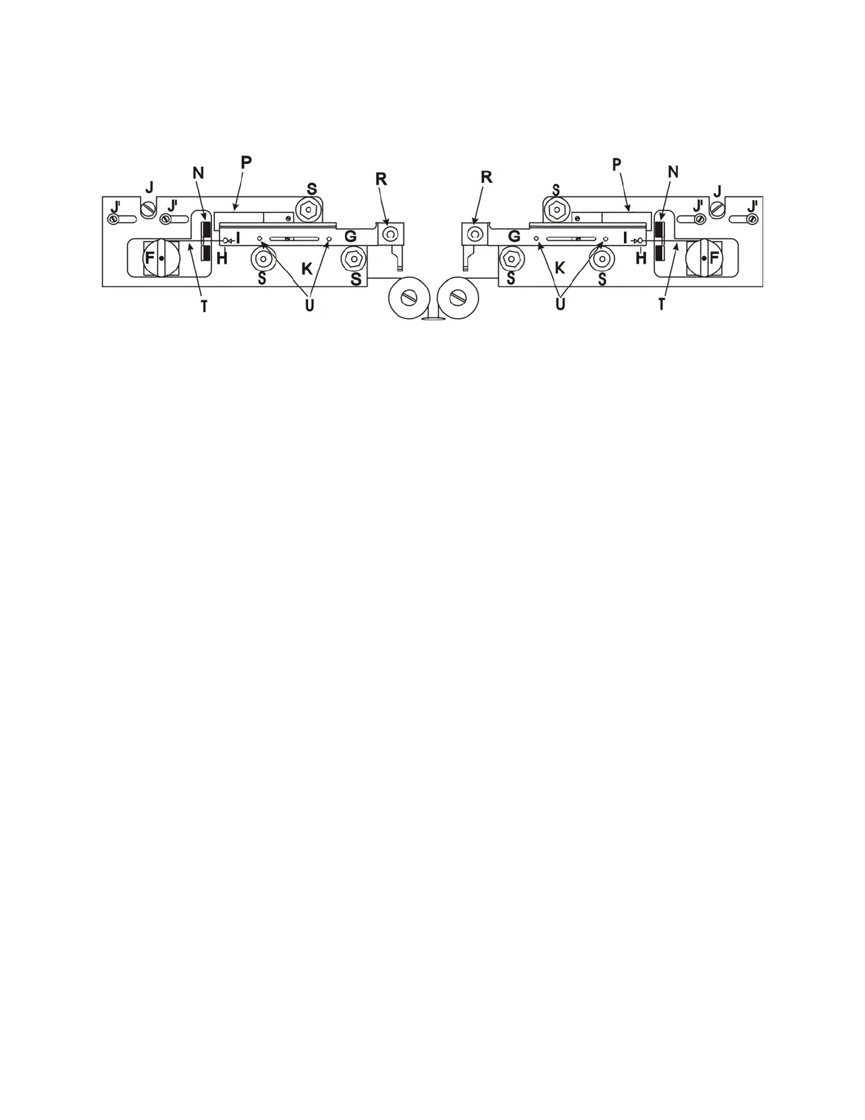
Figure 1-5. Upper cable pulley assembly.
Panels, Left And
Right
(K in Figure 1-5)
The panels are the angled surfaces that provide mountings for the
Puller Bars and their Bearings, the Spring Stops, the Bumpers, and
the Upper Cable Pulley Assemblies. Except for minor differences in
shape, the left and right Panels are mirror images of each other.
Note the three socket-head cap screws that attach each Panel to the
base plate top. These screws are used to align the Puller Bars.
Their adjustment, if necessary, is covered in the Maintenance
Section. Contact Sutter Instrument Technical Support for more
instructions on how the panels are aligned.
Bumpers
(N in Figure 1-5)
The Bumper stops the motion of its associated Puller Bar. Each
Bumper also prevents impact forces from breaking pipettes.
Spring Stops
(P in Figure 1-5)
The Spring Stops are one-way catches that catch the Puller Bars as
they rebound off the Bumpers so as to prevent pipette tip collision.
Puller Bars
(G in Figure 1-5)
This assembly consists of the puller bar, threaded post, electrode
clamp knob, and cable retaining screw. The cable retaining screw
(H) holds the cable in a shallow groove (I) at the end of the puller
bar, and forms the ‘resistance’ against which the cable ends pull.
The puller bar is made of mild steel and coated with a controlled
thickness of hard chrome. Glass is loaded into the groove near the
tip of the puller bar and is held in position by tightening down the
clamping knob (R).
V- Bearings
(S in Figure 1-5)
These bearings are the guides for the Puller Bar motion. They are
made of stainless steel and must NEVER be oiled (see Maintenance
Section). Note that these bearings are mounted on stainless steel
bushings, one of which is round with the other two being
hexagonal. The hexagonal (eccentric) bushings are used to adjust
position and ease of travel of the PULLER BARS (see Maintenance
Section). Do not adjust the eccentrics without additional
instruction.
P-1000 FLAMING/BROWN MICROPIPETTE PULLER SYSTEM OPERATION MANUAL – REV. 3.02 (20161118)