3
1.5 System Description – Mechanical (Puller Anatomy)
1.5.1 Some Basic Information
This section presents a basic mechanical description of the P-1000, with particular emphasis
on terminology. Knowing the names of the various parts greatly facilitates communication
between the investigators and the manufacturer when discussing adjustments or service
problems. In addition, various controls and adjustments on the top of the instrument are
located and described. Those adjustments, which are considered part of maintenance
procedures, are dealt with in the Maintenance Section of this manual.
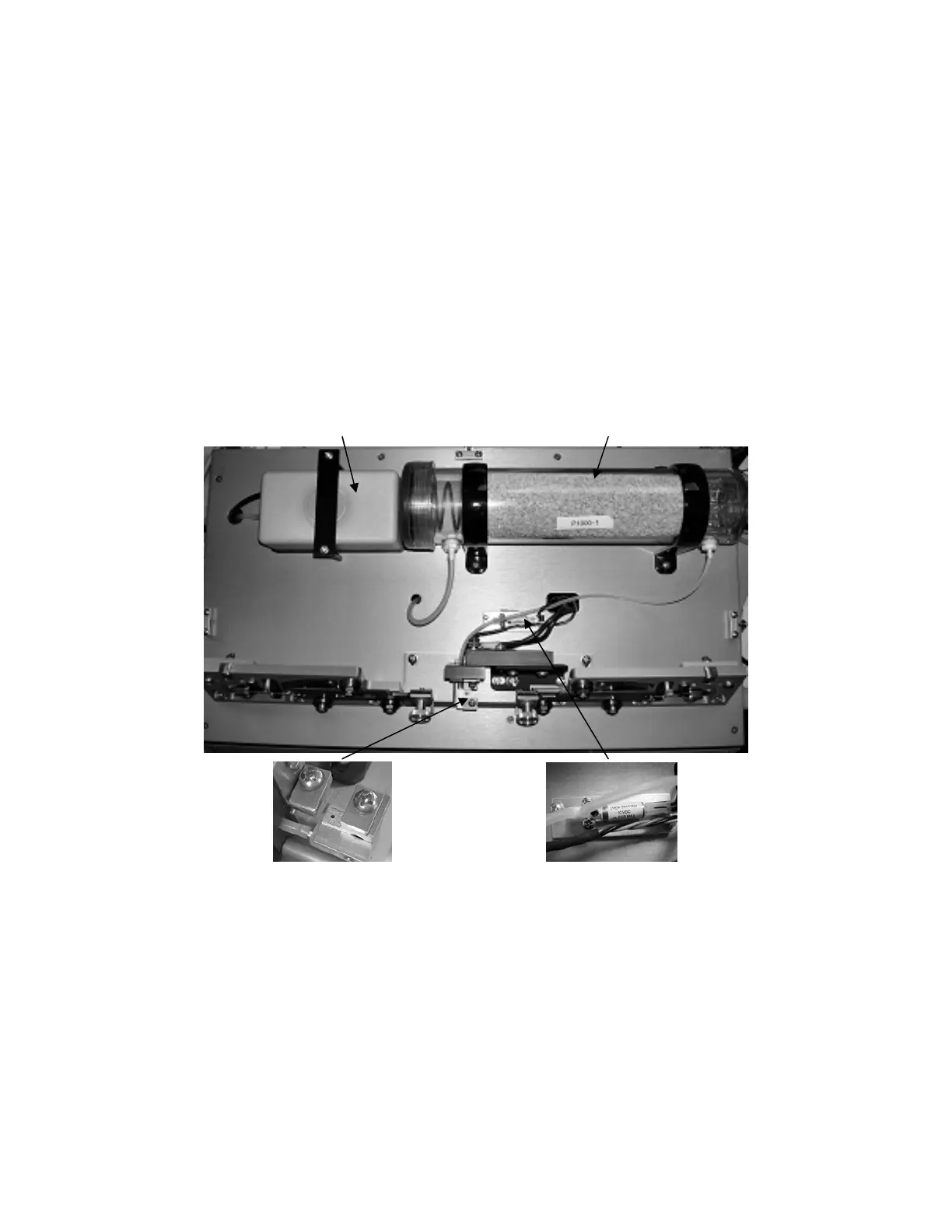
1.5.2 Air Cooling System
The Model P-1000 supplies a blast of air to cool the filament area after the heating segment
of a pull cycle. The components of the air-cooling system are shown below.
Air Compressor Drierite Canister
Air Jet Air Valve Solenoid
Figure 1-2. P-1000 base plate with components detail.
Air Compressor The air compressor (or pump) creates the air pressure used to cool
the filament and glass during the pull cycle.
Air Jet Directs the cooling air to the filament. The air jet should be
positioned 2 to 3 millimeters below the filament. The screw that
secures the air jet to the filament block can be loosened allowing
the jet to move up and down.
P-1000 FLAMING/BROWN MICROPIPETTE PULLER SYSTEM OPERATION MANUAL – REV. 3.02 (20161118)
 Loading...