6
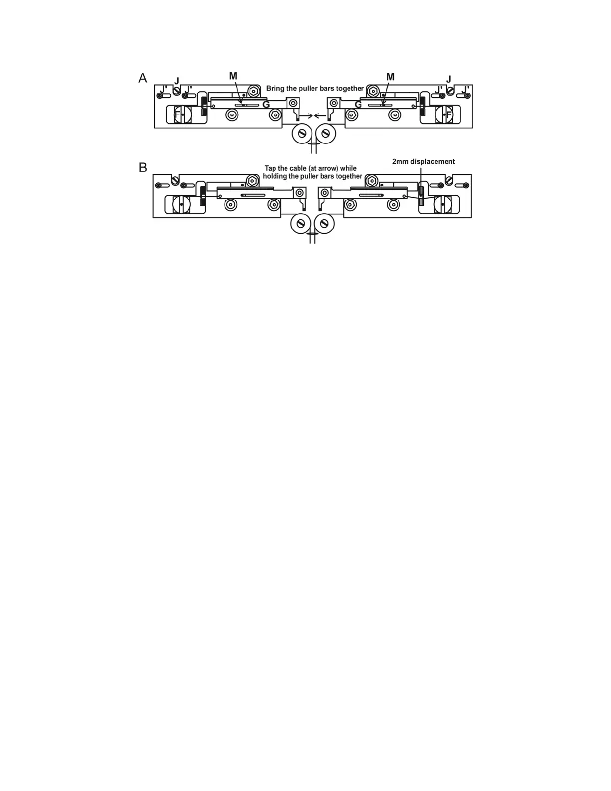
Figure 5-4. Pulley adjustment.
Holding the puller bars together with one hand, you should be able to press on either cable
between the carrier and the pulley and feel about 2mm of deflection (Figure 5-4B) before the
solenoid hits its stop. You will hear a clamping noise inside the chassis when the solenoid hits
the stop. If the deflection is more or less, the pulley position should be changed. This is done
by loosening the two screws above the pulley (J’ in Figure 5-4A) and turning the chrome
eccentric screws (J in Figure 5-4A) to move the pulley in small increments until the two
cables are of equal tension. If the carrier no longer stops against its stop in the slot (M in
Figure 5-4A), but stops against the cable, then the cam must be adjusted back until the
carrier once more hits its stop. It is important that the carriers come up against their stops
without significant tension on the cables. If there is too much tension, the initial pull will
depend on how tightly you hold the finger stops when the glass is clamped in the carriers. If
this happens, the electrodes will not be consistent from pull to pull.
5.4 Regeneration of Drierite Granules
The Indicating Drierite found in the canister at the right rear corner of the base plate on the
P-1000 is a desiccant made of calcium sulfate (97%) and cobalt chloride (3%). This material is
used to remove water vapor from the air-cooling supply system. The drierite granules become
pink as they absorb moisture, eventually requiring that they be “regenerated” (dried).
5.4.1 Removing the Canister
Before proceeding, make sure the puller is off and unplug the power cord. To remove the
canister from the -, first remove the plastic puller cover by loosening the three screws that
hold it down. Next, slide the input (left) and output (right) air tubes off their white plastic
connectors on the canister. Finally, the two black plastic clamps that secure the canister to
the baseplate can be released by removing the screws at the base or, with older style clamps,
forcing one half of the connector out of the other half at the point where they meet.
5.4.2 Replacing the Granules
Unscrew the end cap, being careful not to loose the black rubber-sealing ring that forms the
airtight seal under the cap. With the cap off, the spring, the aluminum keeper, and the first
filter can be removed exposing the Drierite. The exhausted granules can then be removed
from the canister. DO NOT REMOVE THE FAR FILTER AND ALUMINUM KEEPER. The
P-1000 FLAMING/BROWN MICROPIPETTE PULLER SYSTEM OPERATION MANUAL – REV. 3.02 (20161118)