4-16 FI SYSTEM AND INTAKE AIR SYSTEM
Output voltage
(V)
Low
High
Low
High
(High vacuum)
(Low vacuum)
Intake air
pressure(mmHg)
Output voltage
(V)
Low
High
Small
Large
Throttle valve
opening(Degree)
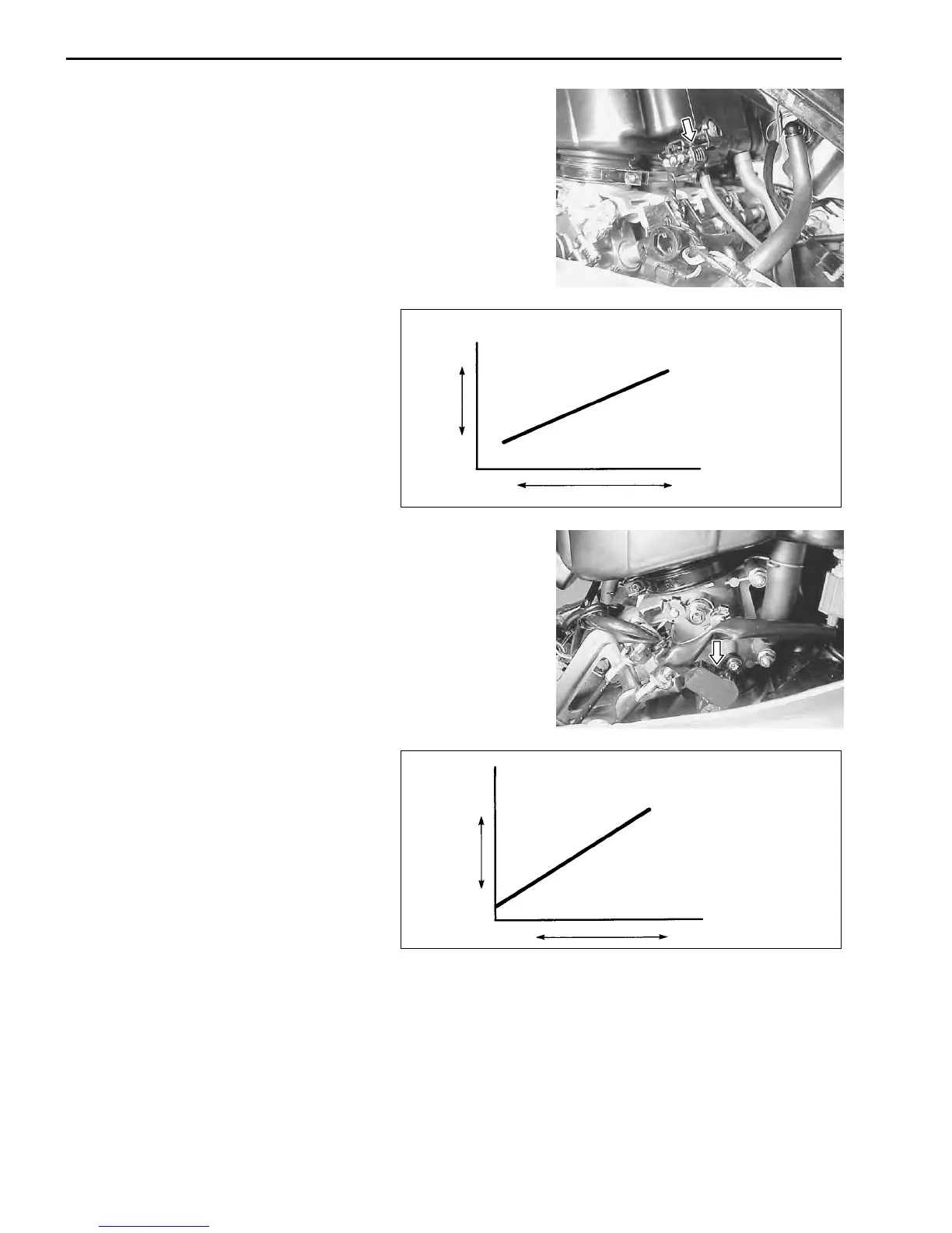
SENSORS
INTAKE AIR PRESSURE SENSOR (IAP SENSOR)
The intake air pressure sensor is located at the rear side of the
air cleaner box and its vacuum hose is connected to the throttle
body.
The sensor detects the intake air pressure, which is then con-
verted into voltage signal and sent to the ECM.
The basic fuel injection time (volume) is determined according to
the voltage signal (output voltage).
The voltage signal increases when the intake air pressure is high.
THROTTLE POSITION SENSOR (TP SENSOR)
The throttle position sensor is installed on the No.4 throttle body.
The throttle position sensor is a kind of variable resistor which
detects the throttle opening angle.
The battery voltage in the sensor is changed to the throttle posi-
tion voltage which is then sent to the ECM.
The basic fuel injection time (volume) is determined according to
the voltage signal (output voltage).
The voltage signal increases as the throttle is opened wider.
 Loading...


