1,3,5-8,10,12,
14,16,19-20,
22-25,28,30,32,3
3,36,38,44-51
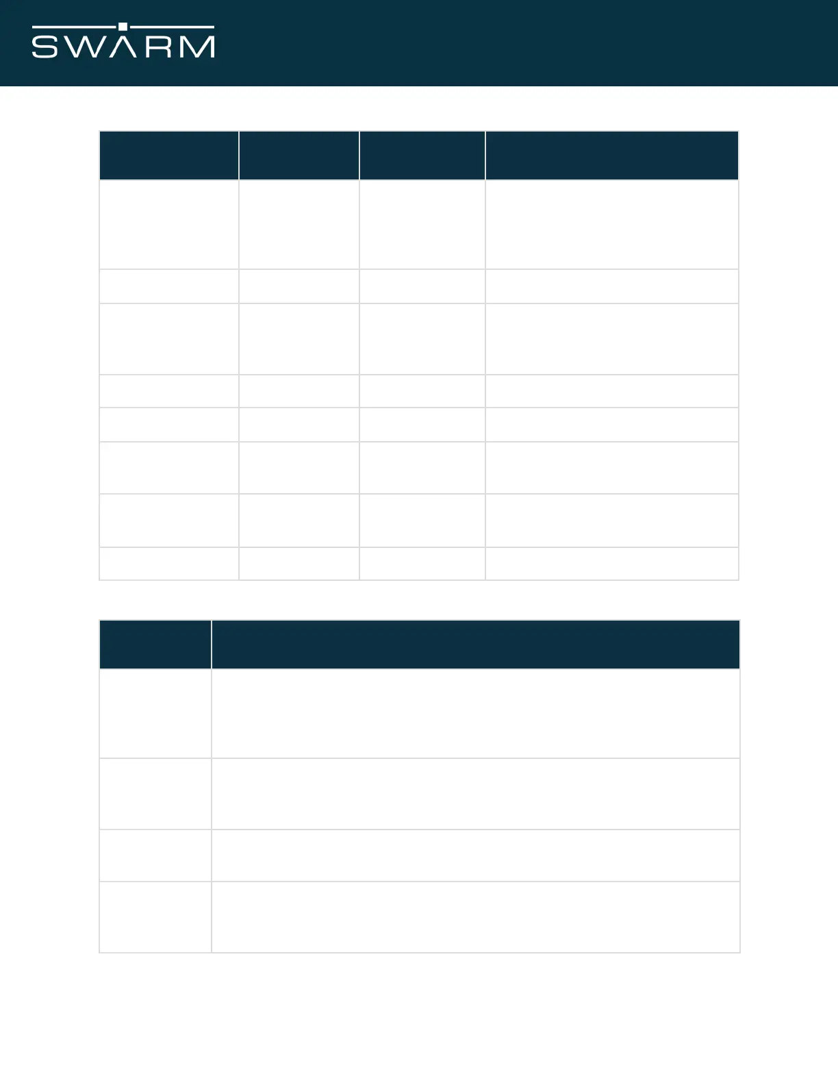
3.3V/5V at up to 1600mA/790mA
4,9,15,18,21,26,
27,29,34,35,37,
40,43,50
Transmit/Receive indicator
*leave open if not used
1 pulse per second
*leave open if not used
General purpose input/output
Table 7: Modem pin numbers and descriptions.
Additional Notes
Connection is unbuffered and connected directly to a GPIO on the Modem
processor. Configuration will be provided via serial commands. GPIO1 pin
is 3.3V tolerant and open drain, with a sink current limit of 8 mA (20 mA
with a relaxed VOL/VOH)
The VDD connection points are in parallel with one another and power the
Modem. If the designer wants to enable a complete power off mode, a load
switch can be provided here
The 1PPS signal is a one pulse per second signal synchronised with GPS.
*leave open if not used
HIGH when transmitting
LOW when receiving
*leave open if not used
Table 8: Additional notes on pin numbers.
November 2021 Swarm M138 Modem Manual - Rev 1.00 14/77