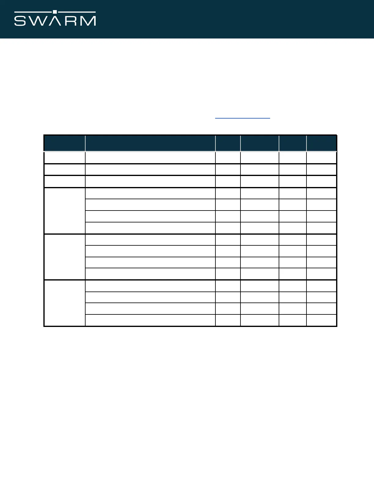
4.3 DC Power Interface
The DC power interface consists of the DC power inputs as summarized in Table 9. The power
requirements apply to DC power measured at the Swarm Modem user connector input and not
at the output of the power supply. It is required that users incorporate the required bypass
capacitors for the supplied power input as can be seen in Design Guidance.
Module supply voltage ripple
Module supply voltage absolute limits
Current consumption - Sleep Mode
Current consumption - Receiver Active
Current consumption - GPS Acquisition Mode*
Current consumption - Transmitter on
Current consumption - Sleep Mode
Current consumption - Receiver Active
Current consumption - GPS Acquisition Mode*
Current consumption - Transmitter on
Current consumption - Sleep Mode
Current consumption - Receiver Active
Current consumption - GPS Acquisition Mode*
Current consumption - Transmitter on
Table 9: Power supply characteristics for 3.3, 4.2, and 5.0V supplies to the Modem.
*Includes satellite receiver active current with GPS in acquisition mode. The Modem enters into GPS acquisition
mode for approximately 30 seconds after exiting from sleep mode, on powerup, or when the Modem needs to
re-acquire a GPS fix (approximately once every 3 hours) while the Modem is continuously powered on and not in
sleep mode.
November 2021 Swarm M138 Modem Manual - Rev 1.00 15/77