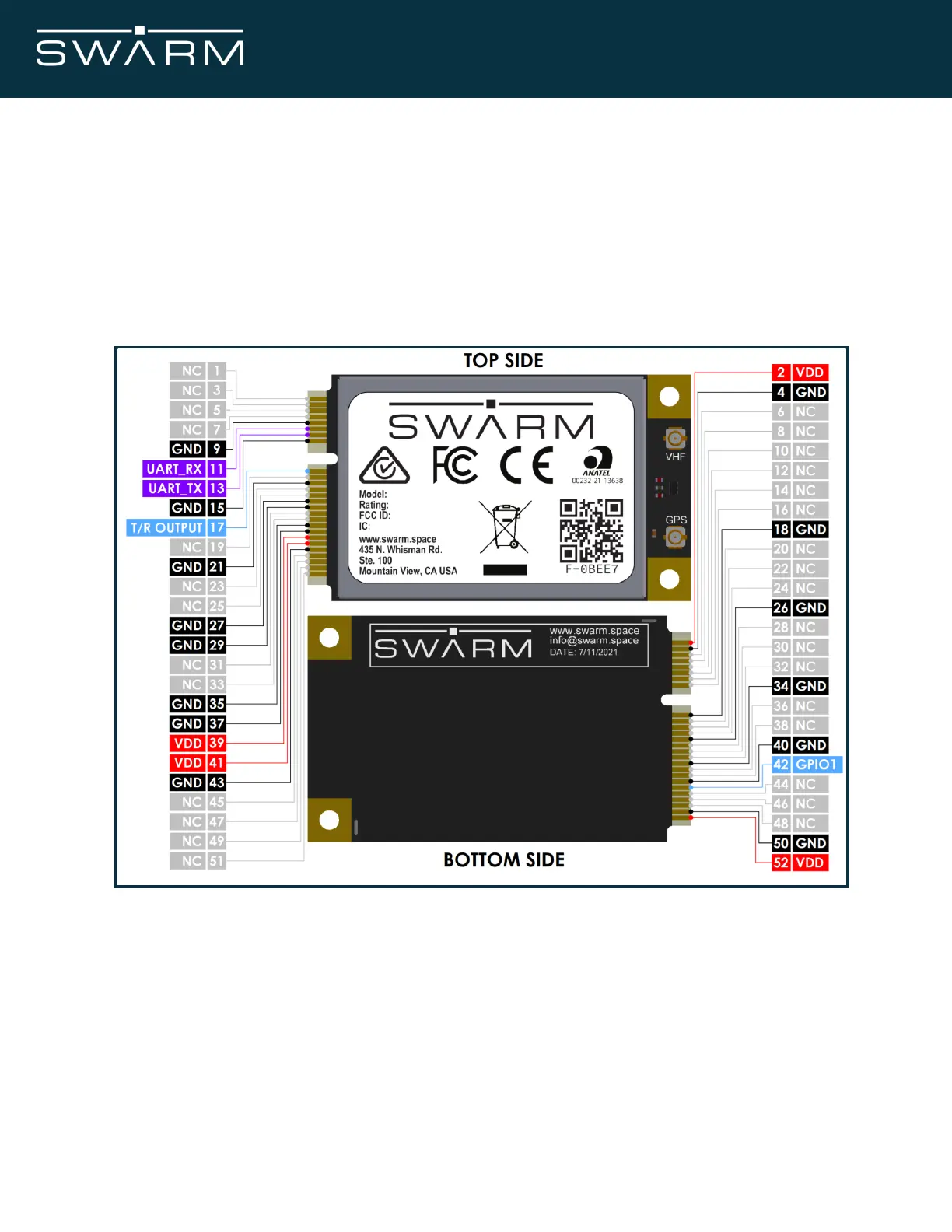
4.2 Modem Pin Allocation
The pin numbering scheme of the Swarm Modem is shown in Figure 4. All pins are located on
the card edge of the Swarm Modem and are designed to fit in a standard mPCIE card
connector. The pin function assignment is given in Tables 7 and 8. Multiple supply grounds are
provided and all power pins / supply grounds are required to be connected to the power supply
in order to limit the current on any one pin. Multiple signal grounds are provided to reduce
cross-talk. Many pins are intentionally left empty, and must be left unconnected.
Figure 4: Modem pinout and pin number
November 2021 Swarm M138 Modem Manual - Rev 1.00 13/77