5 Design Guidance
This section describes the recommended design practices for successful integration of the
Modem.
5.1 Input Connections
The Swarm Modem utilizes standard 51 mm x 30 mm mPCIe form factors that require an
industry standard connector listed below. All voltage pins need to be connected in such a way to
minimize ground loops, often down by using a via to a power/ground plane. A method of
retaining the Modem is also required, whether it be a retaining clip or screws.
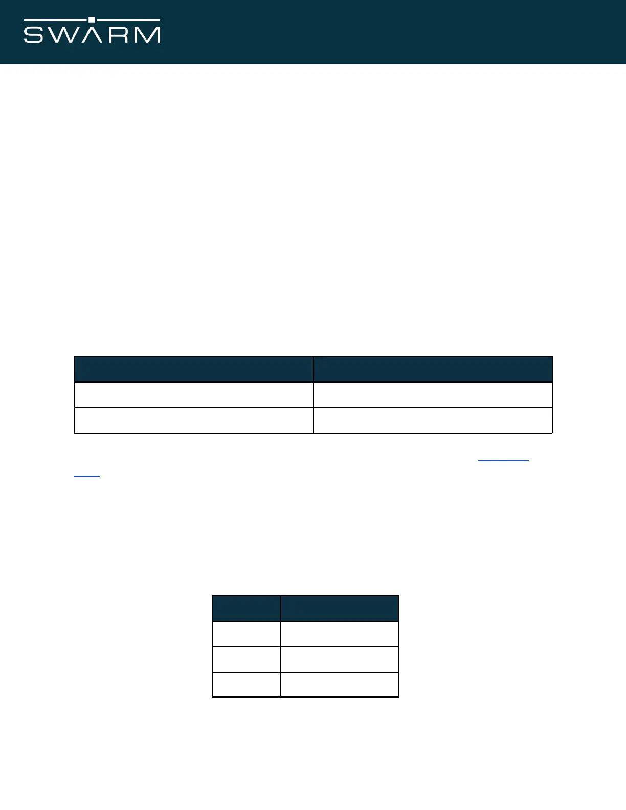
Below are example connectors, retaining clips, and their part numbers. Many vendors and
styles exist from vendors such as DigiKey/Mouser/Newark.
TE Connectivity: 2041119-2
TE Connectivity: 1717832-2
Altium footprints with correct connector/retaining clip spacing can be found in our Developer
Tools .
5.2 Decoupling and Feed-through Capacitors
We require a minimum amount of decoupling capacitance in order to reduce/eliminate any high
frequencies from the input supply reaching the Modem input terminals.
Choose Ceramic capacitors rated for 16V or greater, X5R or better
November 2021 Swarm M138 Modem Manual - Rev 1.00 20/77