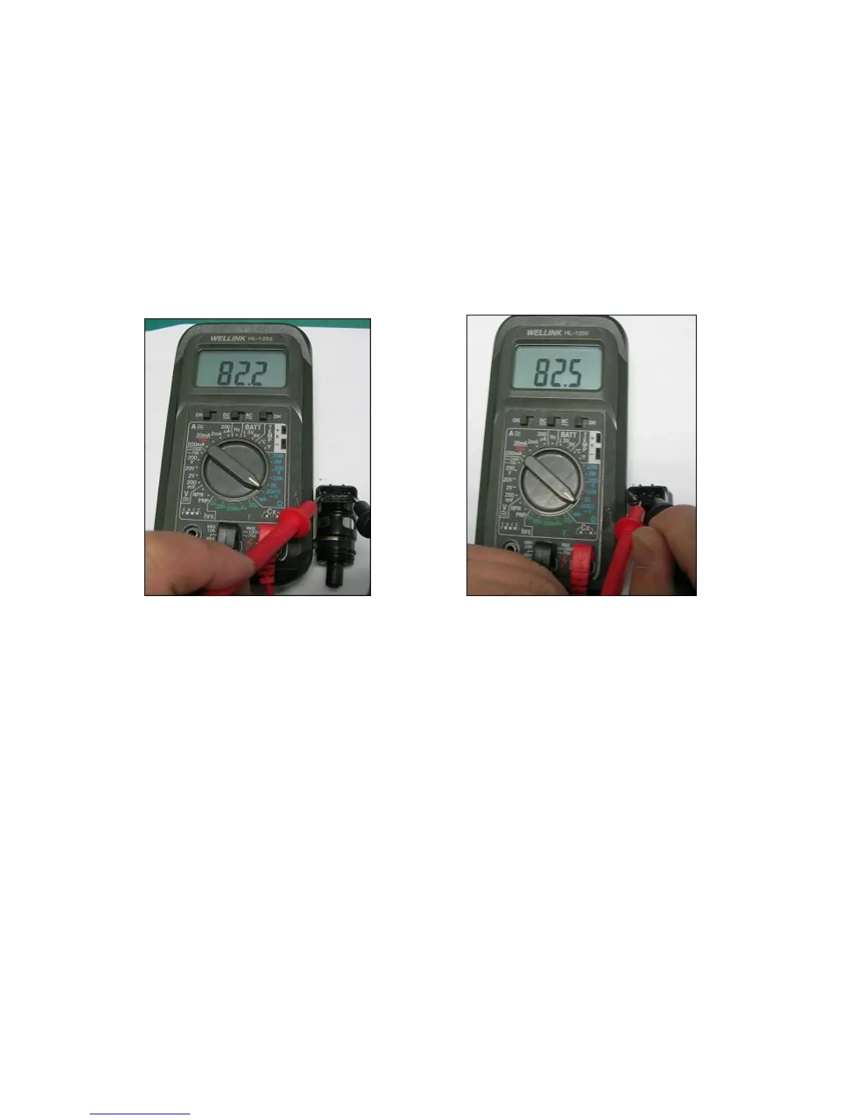
c). There are two phases in the ISC resistance measurement: Phase A and Phase B.
d). The two pins of ISC Phase A are ISCAP and ISCAN; on the other hand, ISC Phase
B are ISCBP and ISCBN.
2. Functional Test: (This test can only done with ISC unit on the throttle body)
a). Key off.
b). Hold the ISC unit with hand
c). Open the throttle fully
d). Key on
e). Feel if the ISC unit is activated or not.
4). Malfunction determination:
a). Resistance in A phase = 80 ± 10Ω (Environment temperature:15 ~ 25℃ )
Resistance in B phase = 80 ± 10Ω (Environment temperature:15 ~ 25℃ )
b). When ISC Stepping Motor is activated, it will vibrate or making some continuous ticking
sound.
5). Abnormal phenomenon and treatment:
a). Bad contact in coupler.
b). Check Wire harness for twisted or bad contact wires.
c). ISC abnormal, replace with a new component