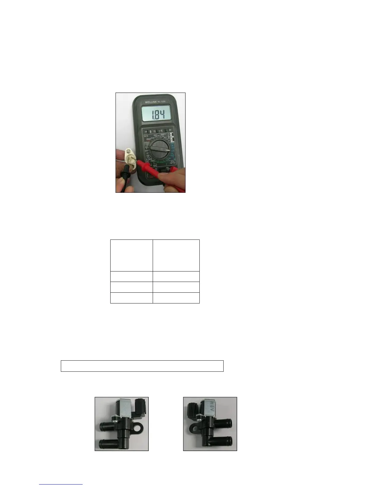
2). Check procedure:
Electrical resistance measurement:
a). Use the Ohm function of electric meter to check the resistance value of AT sensor
(As shown in figure 24 )
3). Malfunction determination:
a). The relationship between electrical resistance value and the environmental temperature.
4). Abnormal phenomenon and treatment:
a). Sensor error or the coupler has bad contact pins.
b). Check wire harness for twisted or bad contact wires.
c). AT sensor abnormal, replace with a new sensor
12、AISV (Air Injection Solenoid Valve)
1). Picture illustration: