INSTALLATION OF:
SHOWER SYSTEMS AND
TUB/SHOWER SYSTEMS
Tools required for installation of this
product are: Phillips screw driver, tubing
cutter, teon tape, soldering equipment,
adjustable wrench and channel-lock pliers.
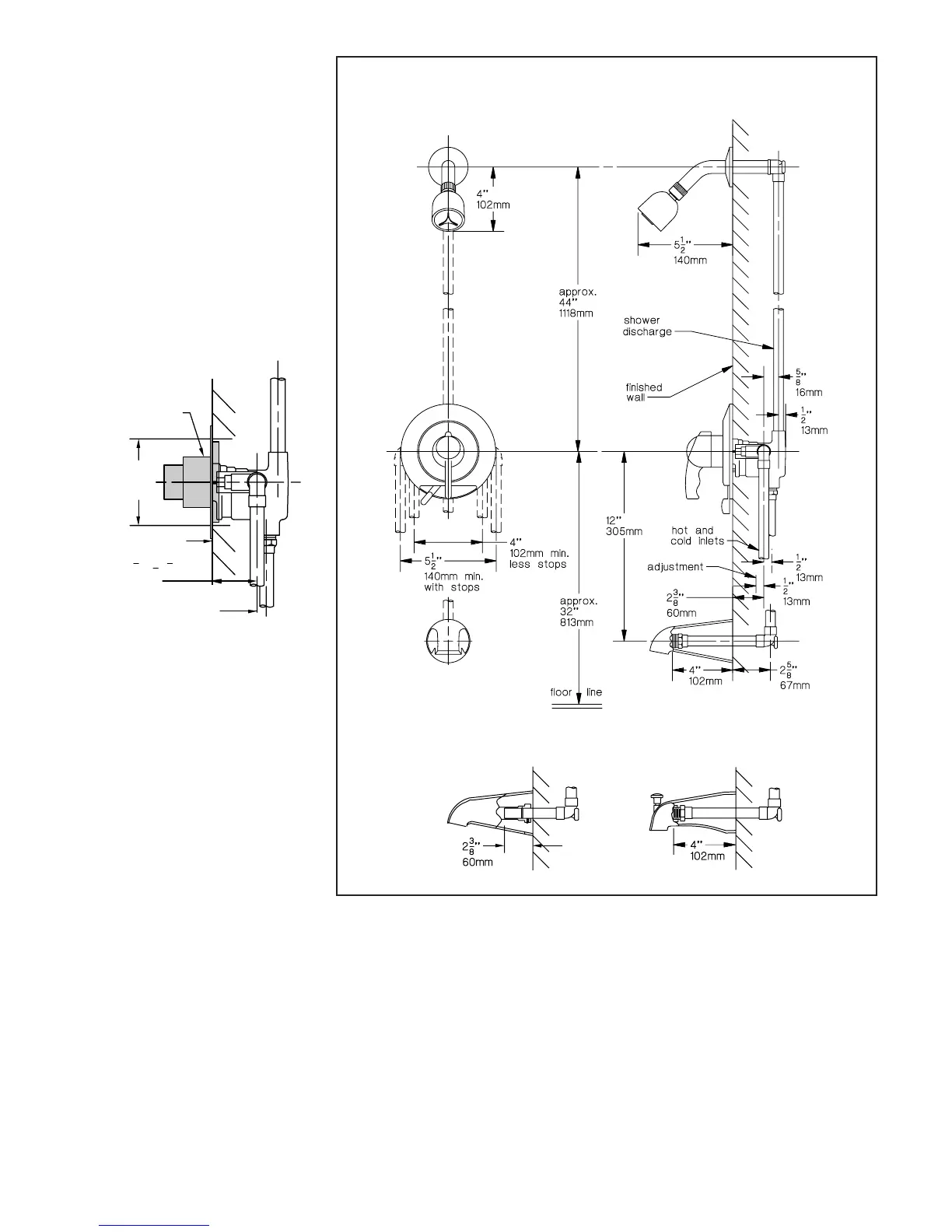
1. Install piping and ttings with valve
body as shown in Figure 2 or 3.
IMPORTANT: Valve rough-in is 2-3/8”
+/- 1/2” from CENTERLINE OF
SUPPLIES TO FACE OF FINISH WALL.
Install so that line indicated on rough-in
plaster shield on valve is ush with
nish wall as shown in Figure 1.
Tub/Shower System (Figure 2)
Model A
Pipe shower head from outlet marked
“S” and to tub spout from outlet
marked “T”. DO NOT SUBSTITUTE
OTHER OUTLET ACCESSORIES FOR
THE TUB SPOUT (such as HOSE
AND SPRAY, SHOWER HEAD,
BODYSPRAY, LEDGE SPOUTS, ETC.)
The diverter-mechanism in this valve is
so designed that it cannot be subject
to any back pressure, other than is
imposed by the spout supplied with
this package. Install HOT on left and
COLD on right according to valve
markings.
Shower System (Figure 3)
Model B
Pipe to shower head from outlet
marked “S”. DO NOT REMOVE PLUG
FROM OUTLET MARKED “T”. Install HOT
on left and COLD on right according to
valve markings.
Tub or Shower System (Figure 2A)
Model C
The valve in this system has a built-in
choke for use with a diverter spout.
Follow the instructions above.
2. When nishing tile wall REMOVE (pull
off; don’t turn) ENTIRE PROTECTIVE
ROUGH-IN SHIELD and FILL AREA
AROUND VALVE BODY WITH GROUT
OR PLASTER.
3. TURN ON HOT AND COLD SUPPLIES,
valve will not operate unless both hot
and cold water are turned on.
4. Unscrew dome cover (T-19/20) and
tighten packing nut (T-17) for positive
frictional resistance to handle turn
throughout adjustment cycle and at
shut-off position. Check valve cap,
packing nut, diverter spindle o-ring and
all valve, pipe and tting connections
for leaks.
5. SET LIMIT STOP SCREW AS DIRECTED
AFTER “IMPORTANT” IN BOLD TYPE ON
PAGE ONE. Reattach dome cover back
onto packing nut.
6. Peel from backing and rmly press
diverter volume dial/emblem (T-143,
T-144) into position on clean, dry
escutcheon (T3-27D) and assemble
diverter volume control lever (T3-30),
shaft (T-154), and clip (T-153) into
escutcheon as shown in Figure 9.
FIGURE 2
Model A: Tub/Shower System
finish wall face
4" (101mm) Max
2
3
8
''
60mm
1
2
''
supplies
C
L
plaster shield
+
3" (75mm) Min
FIGURE 1
Suffix SS: Slip-on type spout
FIGURE 2A
Model C: Diverter spout installation