7. Mount gasget (T3-27B) onto back of
escutcheon with opening at bottom
as shown in Figure 4. The use of
this gasket should not preclude sealing
valve body in wall as directed in
installation step 2.
8. ALLOW VALVE TO RUN IN WARM
POSITION FOR A FEW MINUTES TO
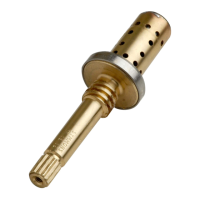
TOTALLY FLUSH SYSTEM. IF SYSTEM IS
QUITE DIRTY, REMOVE VALVE SPINDLE
OR STOP SPINDLES (IF SO EQUIPPED)
TO INSURE PROPER FLUSHING. See
service instructions.
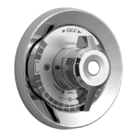
8. Install escutcheon on valve making sure
diverter/volume shaft (A) aligns with
mating key slot in top of diverter/volume
spindle (B) (Models A and B only).
A. B.
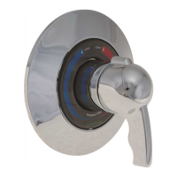
Push assembled escutcheon against
wall and secure to valve with two
escutcheon screws (T3-28). Snap in
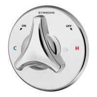
dial/emblem assembly (T3-29). Mount
temperature control handle on valve
spindle spline as shown in gure 9.
Install shower arm, ange and shower
head. See Figures 2 and 3.
9. Do not install positive shut-off devices
on the outlet of this valve or devices
that do not allow the valve to ow at
least 1 GPM at 50 psi inlet pressure.
EXCEPTION: If a self-closing or slow-
closing valve is installed on the outlet,
the supplies of the valve must be
equipped with checks to eliminate hot
to cold by-pass in the event the valve’s
handle is not turned to off after use.
Contact your factory representative or
Symmons directly for information on
available checks.
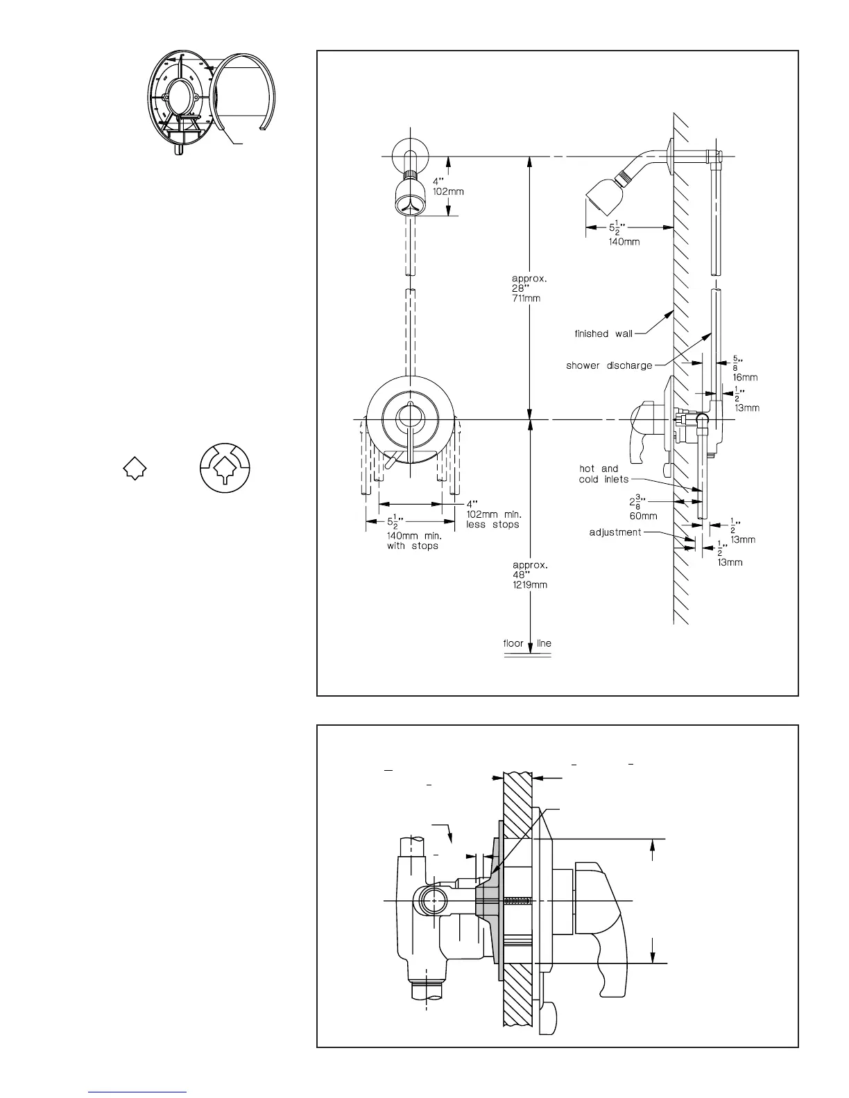
FIBERGLASS WALL INSTALLATION
When installing Temptrol
®
2000 in
berglass or panel walls and it is
desired to sandwich wall between
valve body and escutcheon, cut hole
in wall as shown in Figure 5 and
mount valve with FG-1 wall mounting
ange from rear. Note: It is always
recommended to secure valve piping
to rough construction and not depend
on berglass wall for valve mounting
security. On panel walls over 1” thick,
install in conventional manner.
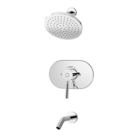
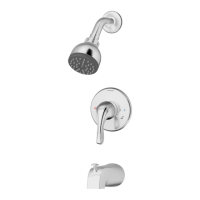
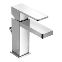
FIGURE 3
Model B: Shower System
THICK WALL
1
16
''
to
3
4
''
2mm 19mm
4" (101mm) Max
3" (75mm) Min
FG Wall Mounting
Flange
1
4
''
6mm
For 21mm to 1" 25mm
thick wall, cut 6mm from
bottom lugs of wall
mounting flange or order
part no. FG-1A
13
16
''
1
4
''
FIGURE 5
FIGURE 4