User’s Manual
Synaccess Networks, Inc. www.synaccess-net.com (760) 930 – 0473 Page 9 of 46
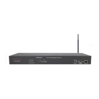
Figure 5 - NP-16 Front and Back Panel Illustration
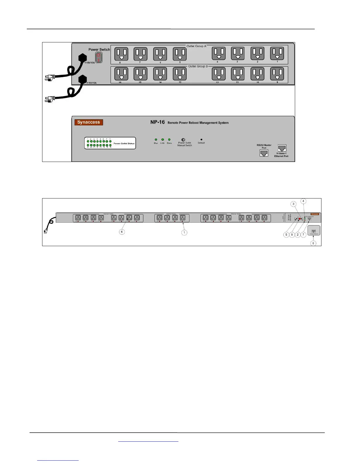
Figure 5A – NPB-20 Front and Back Panel Illustration
1. Power Outlet status LEDs:
Visual indication of user power outlet On/Off status.
2. NP system power On/Off status LED:
Indication of system power On/Off status.
3. Ethernet Link status LED:
When the LED is illuminated, Ethernet port and a LAN connection are established.
4. Ethernet Active data status LED:
When there is data traffic on the LAN, the LED is illuminated.
5. Factory Default Reset switch:
Allow a user to reset the system to factory default settings. The switch is located behind the
small front panel opening.
6. Power Outlet sockets: