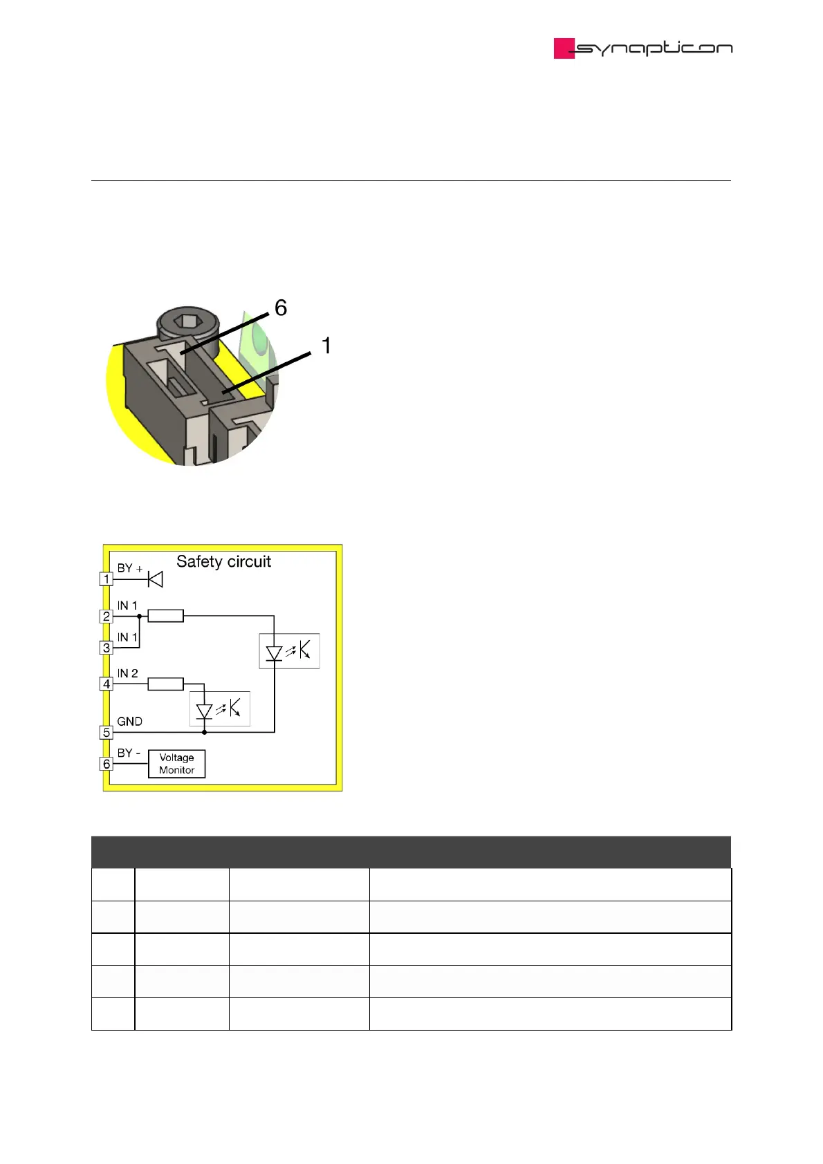
Home
SYNAPTICON
Servo Drives
SOMANET Node Series
SYNAPTICON SOMANET Node Series Hardware Manual
4
of 1
of 1 rating
67 pages
Give review
Manual
Specs
To Next Page
To Next Page
To Previous Page
To Previous Page
Loading...
1.6.3
.1 C
onne
cting
the
STO
/SBC
inpu
ts
1.6.3.1
.1 STO
/SBC
input
port
Pin#
Designa
tion
Function
Descri
ption
1
BY+
Bypass+
Connect to
BY- (Pin
6) to by
pass ST
O/SBC
2
IN1
S
TO/SBC
input 1
Input 1 f
or STO/
SBC
3
IN1
S
TO/SBC
input 1
Extra Pin
for Inp
ut 1
4
IN2
S
TO/SBC
input 2
Input 2 f
or STO/
SBC
5
GND
Safety GND
Must
be isola
ted from
main G
round
Hardwar
e Manu
als / SO
MANET
Node / S
OMAN
ET Node
rev. E.1
© 2021 Sy
napticon G
mbH | Da
imlerstraße
26 | D-71
101 Schön
aich Do
cumentat
ion v 4.10.2
| Built 20
21-07-06
50/67
49
51
Table of Contents
Table of Contents
2
Encoder Port
2
SOMANET Node Rev
5
Technical Specifications
6
Power Specifications
6
General Specifications
7
Maximum Values
8
Load Cycle
9
Downloads
10
Documents
10
CAD Files
10
Hardware Diagrams
11
Ethercat Module
11
Processor Module
12
Drive Module
13
Installation Guide
14
Wiring Instructions
15
Overview of Connectors
15
Power Supply, Phases and Brake
16
Pinout Power Terminal
16
Notes about Choosing the Supply Voltage
17
Using a PELV or SELV Power Supply
18
Warning about Using Contactors Behind the Power Supply
18
Connecting a Brake
19
Encoders and IO
21
Encoder Port
21
Encoder Port 3 / Digital IO
23
Analog in
24
Analog Input Specification
25
Analog Input Resistance
26
Attaching a Voltage Divider
27
Ethercat Port
28
Ethercat in Port
28
Ethercat out Port
29
Connector Details and Mating Parts Numbers
30
Heat Dissipation
31
Thermal Mounting Considerations
31
Mounting Instructions
31
Dimensions
33
Interference with Magnetic Fields
34
On-Site Installation Guide (UL)
36
Branch Fuse Required
36
Field Wiring Terminal Marking
37
Downloads
38
LED Signals
39
Overview
39
Legend
39
Core LED
40
Firmware
40
Bootloader
41
Drive LED
41
Com LED
42
SOMANET Node Safety (Original Instructions)
43
Dimensions
44
Specifications of the Safety Functions
45
System Requirements
45
Technical Specifications
45
Block Diagram
47
Setup of the Safety Functions
49
Connecting the STO/SBC Inputs
50
STO/SBC Input Port
50
Wiring Examples for the STO/SBC Inputs
51
Manual Switch
51
Safety PLC (Plus-Minus Output)
52
Safety PLC (Plus-Plus Output)
52
Connection Diagram for the Brake
53
Brake Power Output (STO/SBC)
54
Connector Mating Parts and Cable Lengths
55
Using the Safety Functions
56
Timing Diagrams
56
Timing Diagram for STO-Function Without Connected Brake
56
Timing Diagram for STO-Function with SBC-Function
57
Fault Diagnostics
59
Fault Reaction
59
Truth Table for Digital Inputs
59
Diagnostic Functions
59
Resetting Diagnostic Faults
60
STO-SBC Status Register
60
Examples for Realising Safety Functions
62
Prevention of Unexpected Start-Up
62
Stop Category 0 (STO)
62
Stop Category 1 (SS1)
63
Prerequisites
63
Wiring
64
Configuration
64
Verification
65
Commissioning and Maintenance
66
Commissioning
66
Maintenance
66
Changelog of the Safety-Related Documentation
67
Other manuals for SYNAPTICON SOMANET Node Series
Manual
887 pages
Documentation
27 pages
4
Based on 1 rating
Ask a question
Give review
Questions and Answers:
Need help?
Do you have a question about the SYNAPTICON SOMANET Node Series and is the answer not in the manual?
Ask a question
SYNAPTICON SOMANET Node Series Specifications
General
Brand
SYNAPTICON
Model
SOMANET Node Series
Category
Servo Drives
Language
English
Related product manuals
SYNAPTICON SOMANET Node 400
887 pages
SYNAPTICON SOMANET Node 1000
887 pages
SYNAPTICON CIRCULO 7
887 pages