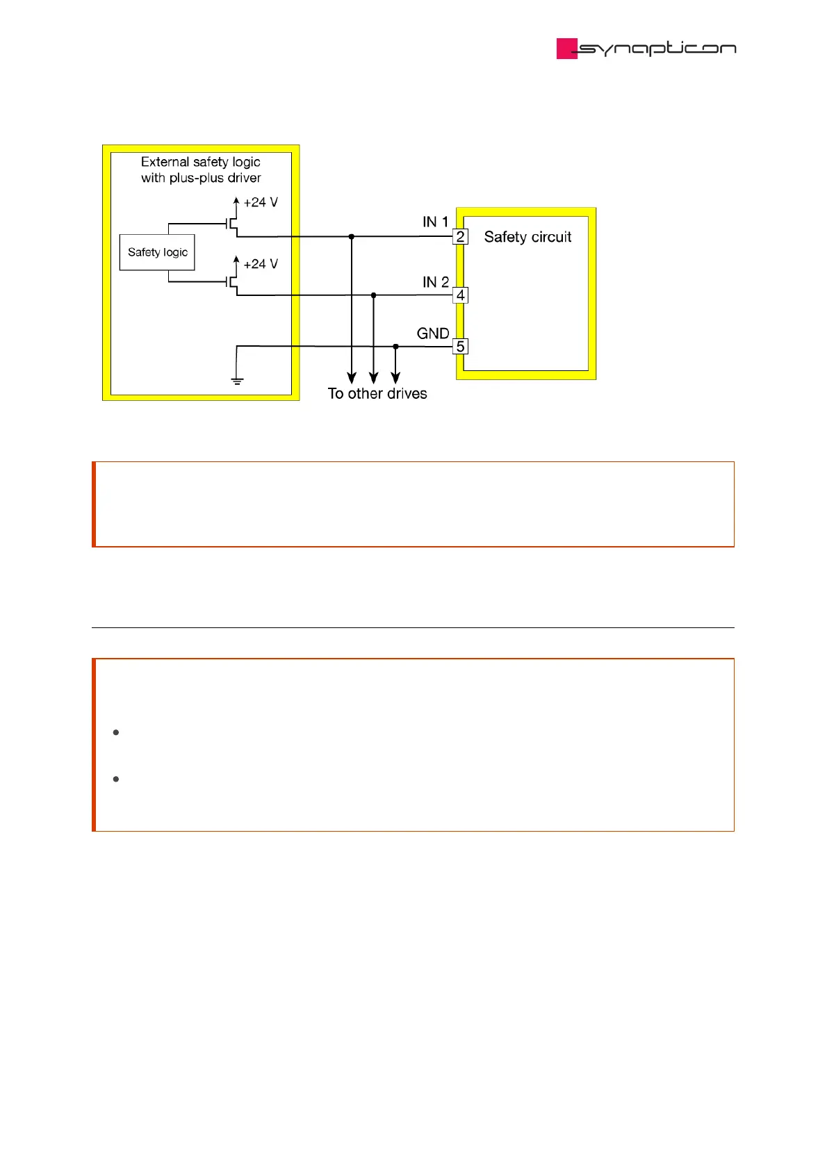
EasyManuals Logo
Home>SYNAPTICON>Servo Drives>SOMANET Node Series

SYNAPTICON SOMANET Node Series Hardware Manual

Default Icon
67 pages
To Next Page IconTo Next Page
To Previous Page IconTo Previous Page
Page #53 background imageLoading...
Page #53 background image
Attention
In case of multiple drive connection, ensure that the output driver has sufficient current driving
capability.
1.6.3.2 Connection diagram for the brake
Attention
Phase D can’t be used for connecting a brake when Node Safety is used:
use the safety brake connector of the safety circuit (SBC out) instead of phase D of the drive
circuit.
ensure to connect the brake GND signal to the Brake- signal of the safety circuit (SBC out)
instead of the general GND.
Hardware Manuals / SOMANET Node / SOMANET Node rev. E.1
© 2021 Synapticon GmbH | Daimlerstraße 26 | D-71101 Schönaich Documentation v 4.10.2 | Built 2021-07-06 53/67

Table of Contents

Other manuals for SYNAPTICON SOMANET Node Series

Questions and Answers:

Question and Answer IconNeed help?

Do you have a question about the SYNAPTICON SOMANET Node Series and is the answer not in the manual?

SYNAPTICON SOMANET Node Series Specifications

General IconGeneral
BrandSYNAPTICON
ModelSOMANET Node Series
CategoryServo Drives
LanguageEnglish

Related product manuals