Getting Started
SYS TEC electronic GmbH 2001 L-487e_6
17
2.2
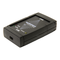
Status LEDs on the USB-CANmodul
A description of the power and status LEDs is shown in the table
below:
USB-CANmodul
connected
LED green
(Power)
LED red
(Status)
Description
no off off No voltage is supplied to
the USB-CANmodul.
yes on Blinking
(at. 10 Hz)
USB-CANmodul logs in to
the host-PC
yes on on Log-in successful, CAN is
not initialized, no error.
yes on off CAN is initialized, no
error.
yes on Blinking
(at. 2 Hz)
An error occurred on the
USB-CANmodul.
Table 1: States of the LEDs on the USB-CANmodul
2.3
CAN Supply Voltage
The default setting for the CAN supply voltage is optically isolated.
The voltage for the CAN transceiver and the opto-coupler must be
supplied via the CAN cable. A voltage in the range between +7V and
+13V is recommended. The pin assignment for the DB-9 CAN
connector is shown in the table below:
Pin Signal
1N/C
2 CAN-L
3 GND
4N/C
5 N/C (CAN shield, optional)
6 GND (optional)
7 CAN-H
8N/C
9 Vcc (+7 to +13 VDC)
Table 2: Pinout of the DB-9 Connector