10 I56-6304-000
DOS AND DON’TS WITH FAAST LT-200 DEVICES
Pipe network and device installation
DO:
● Clean any residues of swarf and burrs after drilling holes.
● Use the appropriate accessories in environments with
condensing humidity, to prevent moisture from entering the
device. (e.g. water trap.)
● Use appropriate lters in a dusty environment and avoid
vertical pipes feeding directly from the ceiling into the detector;
use elbows or U shaped pipes.
● Use the bracket supplied to mount it on the wall.
● Use IP rated glands on all cable entry points.
● Plan for sucient space at the side of the detector to allow the
front panel door to open fully.
● Check that all the pipes are tting together properly and there
are no air leaks or partial blockages.
● It is preferable that the exhaust is returned to the sampling
area wherever possible; this type of piping conguration will
minimise pressure dierences across the aspirating unit and
reduce the likelihood of short term ow faults.
● It is recommended that the inlet and outlet connections remain
plugged prior to use, and the outlet is temporarily sealed if the
device is turned o during maintenance periods to prevent
ingress of creepy-crawlies.
DO NOT:
● Use compressed air around the unit. If compressed air is used
to clean the pipework, completely remove the pipe connection
with the FAAST LT-200 detector. Also any cleaning of the pipes
with a vacuum cleaner must be done with pipes disconnected.
● Bend the pipes; use 45° or 90° swept bends.
● Glue the pipe entering the inlets or outlets of the FAAST LT-200.
The product is designed to fasten without glue. Certain glues
could damage the plastic of the device. If excessive glue is
used it may enter into the device and compromise the internal
functioning. Devices with glued pipes are automatically classed
as out of warranty because they cannot be tested.
● Use the device in a corrosive environment.
● Install the product on the ceiling, or in any orientation other than
vertically on a wall.
● Drill the detector case without using a sealing gland; this will
compromise its IP rating.
Device operation and maintenance
DO
● Take particular care when removing the lters, in order to avoid
dropping any dirt or waste materials into the device or fan area.
● Always turn the aspiration system o and close sample holes
when building or other dusty works are in progress on the
installation site. Any un-piped outlet should be temporarily
sealed if the device is turned o during maintenance periods.
● Ensure the lter gasket is tted after cleaning or changing the
lter.
DO NOT
● Use aerosol smoke to test the device alarm. Canned test
smokes contain oily substances that can leave a residue and
may damage the device.
● Test the device with the inlet and/or outlet closed.
● Clean any area around or inside the device with compressed
air. If compressed air is used to clean the pipework, remove the
pipe connection with the FAAST LT-200, or install the System
Sensor Reverse Flush Pipe Cleaning unit. Any cleaning of
the pipes with vacuum cleaner must also be done with pipes
disconnected from the FAAST LT-200.
● Clean the device with any type of solvent, always use a clean
cloth.
● Insert anything into the inlet, outlet openings, or the lter, laser
sensor or the fan areas.
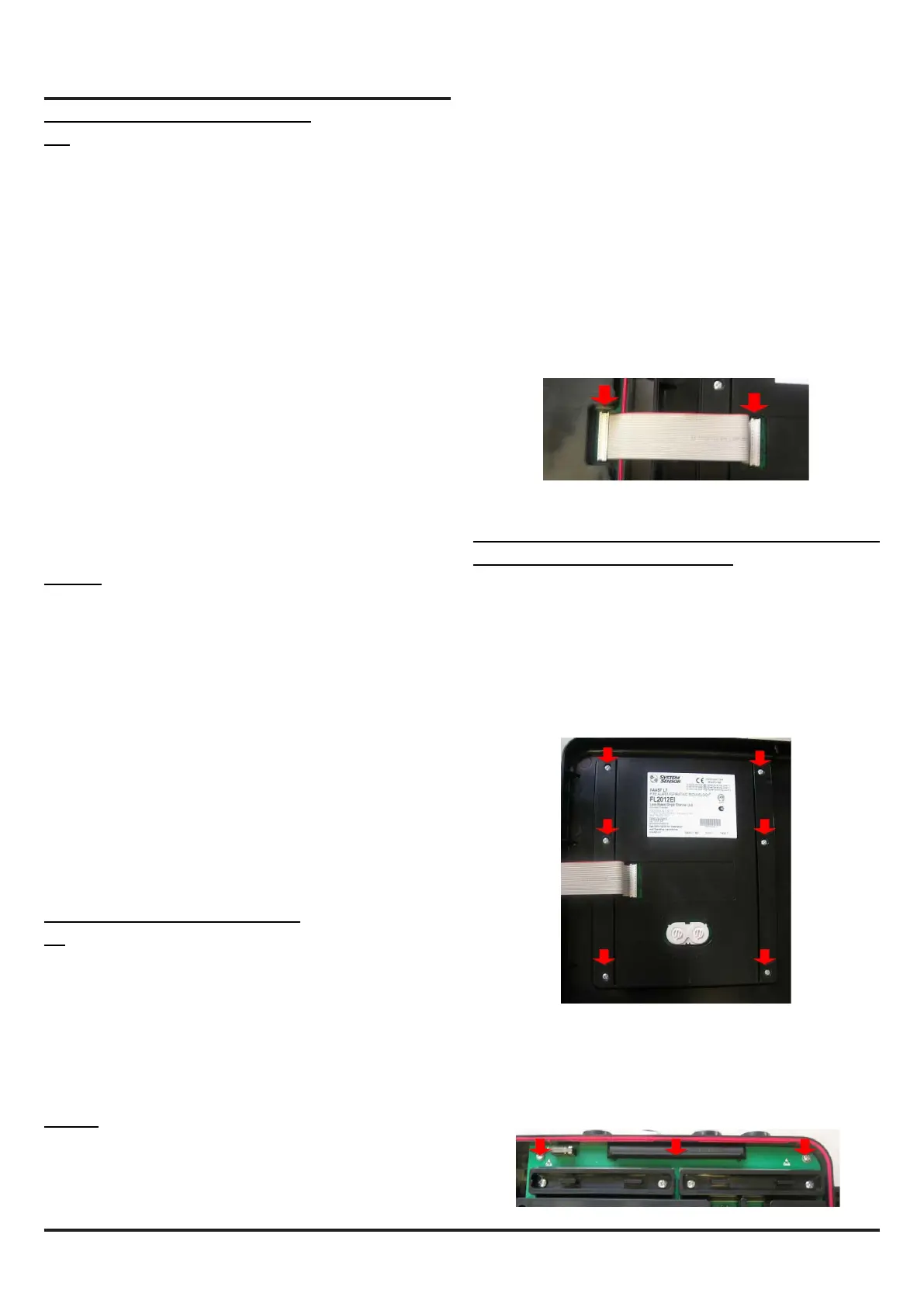
● Do not remove the exible cable connecting the PCB to the
front panel. (Figure 5: red arrows). This could compromise a
reliable connection between the two PCBs.
Figure 5: PCB cable
Actions that could aect the operability of the detector:
DO NOT DO ANY OF THE FOLLOWING:
● Glue the pipes into the inlet or outlet connections of the FAAST
LT-200 detector.
● Remove or loosen the screws (Figure 6: red arrows) xing the
PCB cover mounted onto the front panel. This could damage
the PCB or the electronic components mounted on it, and
compromise the sealing protection of the gasket.
Figure 6: Front panel PCB cover
● Loosen or remove the screws (Figure 7: red arrows) xing the
PCB on the main box. This compromises the sealing of the
device.
Figure 7: Main PCB xing screws