8 I56-6304-000
LT-200 unit has been set to Maintenance mode. (PipeIQ v2.9.1 or
higher) is available on the USB stick provided with the FAAST LT-
200 unit or from www.faast-detection.com).
For PCs running Vista, Win7 or later, the PC will automatically
detect the new hardware, then nd and install the necessary driver
software.
Communicating with a FAAST LT-200 Device
Connect the USB cable to the FAAST LT-200 device as described
above.
In PipeIQ, open the project le (.mdf le) that is associated with the
FAAST LT-200 device being used.
(If no project le is available, click on New and create a new project.
Accept the PipeIQ disclaimer, select the measurement units,
device type and number of channels. Make sure that the device
type selected matches the type of FAAST LT-200 device being
used. The project will assume the factory default conguration for
a device.)
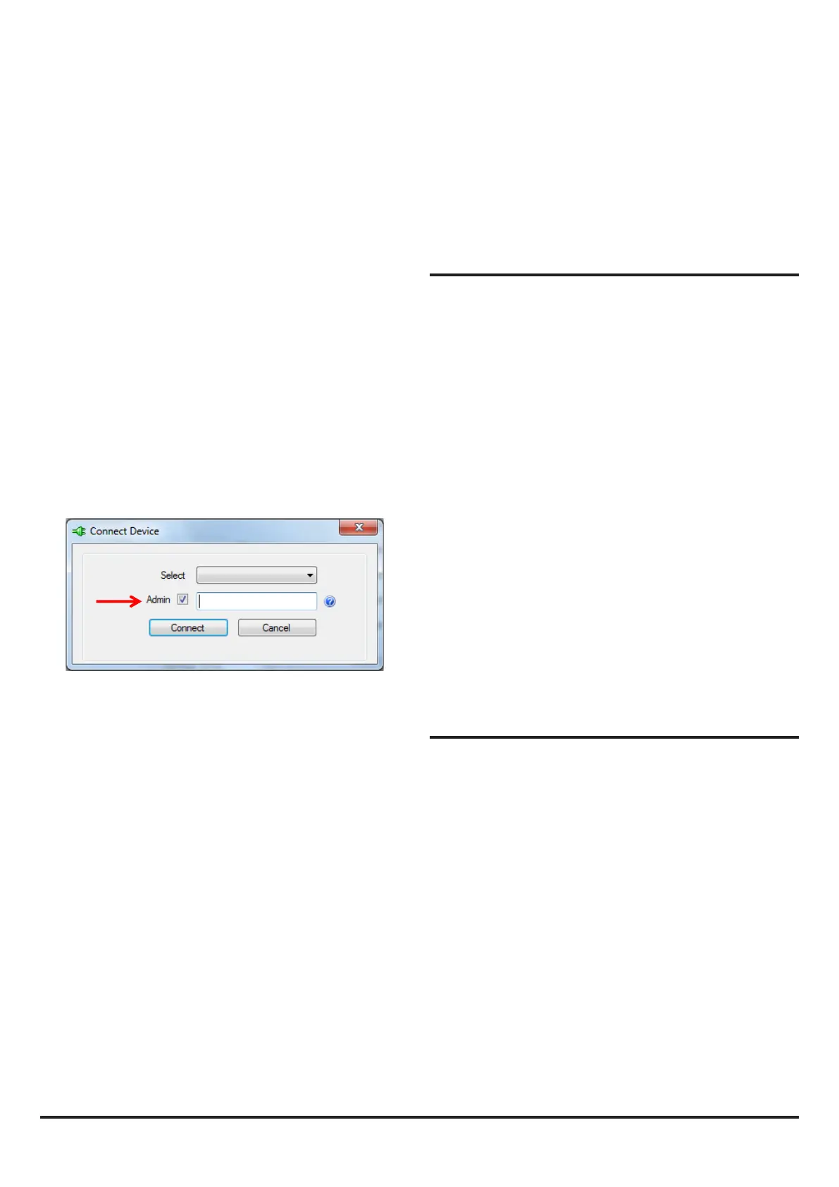
In the Left Hand pane of PipeIQ, left click on the FAASTLT Device
in the system tree to highlight it. Right click on the FAAST LT-200
icon in the left hand pane to reveal the menu. Click on Connect
Device.
Note that to use the full range of connection options, a user must
be connected to the FAAST LT-200 device as an Administrator.
Tick the Admin box and enter the Administrator password to
access these extra commands. The Administrator password is the
same as the Remote Maintenance password (the default is 3111).
This does not aect the physical USB connection to the unit.
Because the Remote Maintenance state does not have a time-out,
the physical connection can be maintained indenitely.
To leave the Remote Maintenance mode, unplug the USB cable
from the FAAST LT-200 device and rmly lock the door. The unit
will return to the Maintenance state. The FAAST LT-200 device
can be reset to normal mode using the front panel buttons, or the
device will automatically revert to Normal mode after 5 minutes
(default setting).
Note that if the door is not shut within 5 minutes of removing the
USB cable, the FAAST LT-200 unit will enter the Service mode.
SETTING THE FAN SPEED
A default air velocity reference value is set into each FAAST unit
before leaving the factory. This equates to an optimum air ow
of approximately 45 l/min. Default high/low ow limit thresholds
are set to guarantee a ow fault when the air ow is ±20% of the
reference ow.
The FAAST LT-200 fan speed in each channel can be set to Auto
or Manual control.
Auto Mode
In automatic fan speed mode, the unit will initialise when it is turned
on and nd the best fan speed to give the reference air ow value.
Auto fan mode is the detector’s default setting and is likely to be the
preferred setting for the majority of aspirating installations. Every
time the detector is powered o and on again, it will re-initialise the
fan speed to achieve the correct reference ow value.
Manual Mode
In manual fan speed mode, the unit uses the fan speed dened
in the conguration, and does not optimise the fan speed to the
dened reference ow value. The fan speed can be set to operate
in the range between 1 and 10 (highest speed). One of the main
uses for the manual fan mode is for testing an installation and
checking transport times etc.
Fan Speed Indication
It is possible to check the fan speed setting using the front panel
push buttons (Reset and Disable). The speed value is displayed
for a short period on the alarm level LEDs (fan speeds 1 – 10). For
more details of this function, see the Front panel buttons – what
they do section.
FAAST LT-200 ALERTS AND FAULTS
The FAAST LT-200 unit signals two types of warnings (see Table
2): these are categorised as faults (major troubles) and alerts
(minor troubles). To indicate an alert or a fault, the device uses
specic LEDs.
When one or more faults occur, the general fault LED is turned
ON and the general fault relay is activated. A general fault can be
latched, or not, based on the programmable options (the factory
default is Not Latched.)
With the default settings, Alerts do not set the general fault
condition. However some faults or alerts can be used to set an
auxiliary fault relay if programmed to do so. In this case they will
also set a general fault at the same time. An auxiliary fault can be
latched, or not, based on the conguration.
Fault delay
A user can congure a delay between a general fault condition
and fault relay activation. During the delay, if the fault condition is
cleared, the relay will not be set.
When a fault occurs, an individual fault LED will be set ON, or
starts to blink, depending on the trouble. The general fault LED
will also be set on. If a fault delay is programmed the general fault
LED will blink until the delay has nished and if the trouble is still
present, the general fault LED becomes xed ON and the fault
relay switches.
Click on Connect. The detector is connected when a small green
tick is indicated on the device icon. FAAST LT-200 Connected is
shown at the bottom left corner of the screen.
Depending on what operations are required, select the
Conguration, Design or Monitoring tab at the bottom of the screen
as necessary.
The Send Conguration option in PipeIQ™ enables a saved
conguration to be sent to a FAAST LT-200 device. (A user must
be connected to the device as an administrator to access and
perform this command - see above).
Note: When changing the conguration of a FAAST LT-200 detector,
it is necessary to restart the detector following the conguration
download to accept and run the new one. Before this is done, the
detector will continue to operate with the old parameters.
Restart the FAAST LT-200 unit by exiting the Maintenance mode.
Disconnect the PC and remove the USB cable, close the front
cover and wait for the Maintenance mode time-out (alternatively,
press the three front panel buttons for 2 seconds - see Front panel
buttons – what they do section). The device will restart and re-
initialise, running the new conguration.
Disconnecting a FAAST LT-200 device from a PC
In PipeIQ, it is possible to notionally ‘connect’ and ‘disconnect’ the
software application from the FAAST LT-200 device. Right click on
the FAAST LT-200 icon in the left hand pane to reveal the menu.
Click on Disconnect Device; Device disconnected is shown at the
bottom left corner of the screen.