2 I56-6304-000
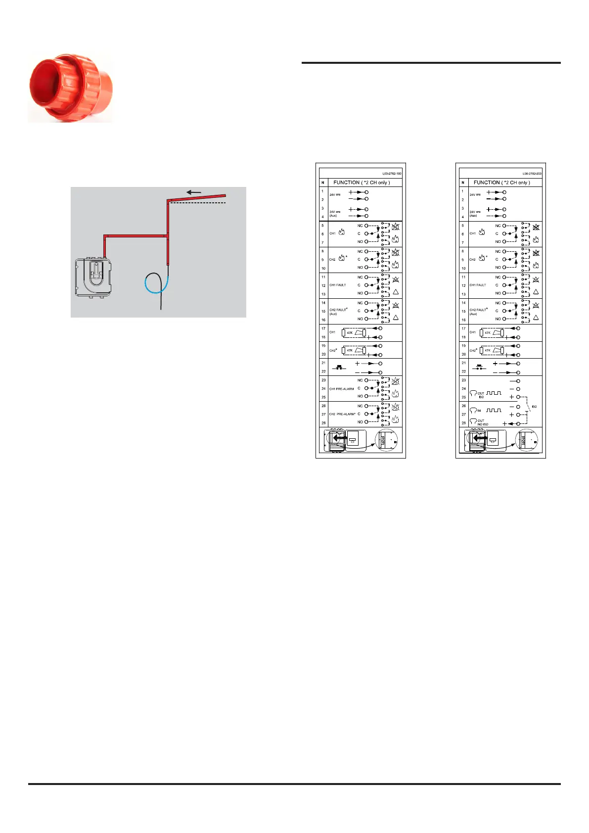
Figure 1A:
Stand-alone connections
Figure 1B:
Loop-based connections
WIRING UP A FAAST LT-200 UNIT
Figures 1A and 1B show the terminal connections for FAAST
LT-200 devices. The stand-alone units (FL0111E, FL0112E and
FL0122E) are slightly dierent from the loop based devices
(FL2011E, FL2012E and FL2022E - Note: Other OEM Brands may
use dierent model numbers).
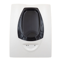
Use a socket union joint to simplify
device removal without the need to move
pipework.
Pipe Angled
Towards Trap
Capillary Primed
with Water
(No Air
Through Trap)
In damp or humid environments, be sure to t a water trap in
the pipeline before the FAAST LT-200 unit so that no liquids are
drawn into the aspirating detector. Make sure that the water trap
does not run dry or the FAAST LT-200 operation could become
compromised.
Power connections and supervision
The primary 24V power supply to the unit should be connected
to terminals 1 & 2. Terminals 3 & 4 are available for a secondary,
standby power unit if required. Terminals 1 & 2 have supervision
monitoring set as a factory default (terminals 3 & 4 are not
supervised as a default). With default settings, connecting power
to T3 & T4 without connecting T1 & T2 will give a power fault.
Sounder EOLs
The sounder output circuits have supervision monitoring and
should be tted with 47K EOL resistors. Without the EOL resistors,
the device will give a sounder fault.
Programmable input (Reset)
There is a programmable input that can have several alternate
functions. As a factory default it is congured as a Reset input that
will reset all alarms and relays. It is intended to be switched using
volt free contacts that are normally open. Leave the input open
circuit if not used.