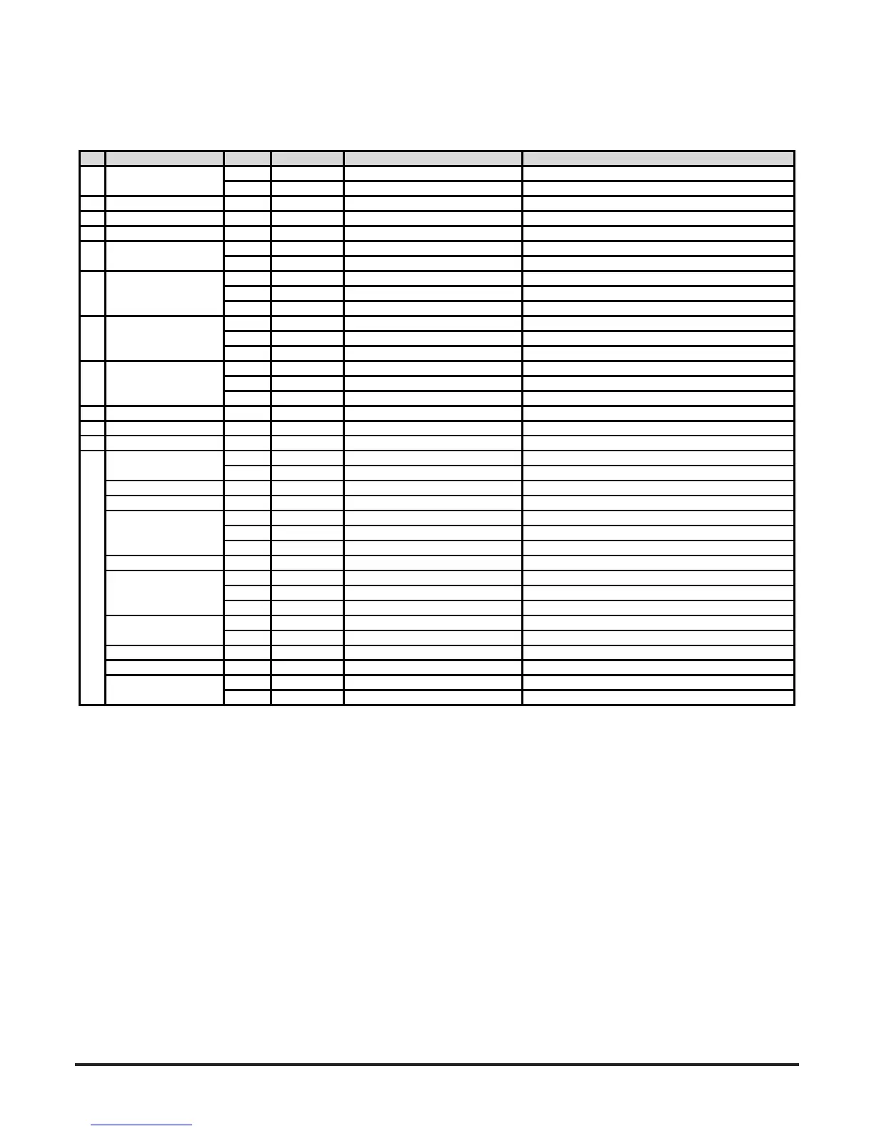
Table 1B Loop based device
(For position of the indicators (ID) on the front panel, see Figure 2B)
ID
Indicator Colour Action
Meaning Notes
Red** ON
ChannelinFireAlarm Firerelayisset
Green Blink
Whensensorpolledbypanel Innormaloperation
2 PREALARM Yellow+ ON
Channelisinpre‐alarm OnlywithpanelsusingAdvancedProtocol
3 SMOKELEVE
Yellow+ ON
Showsalarmlevelreached Numbers1‐9onlyused(needsAdvancedProtocol)
Green* ON
Outputset Controlledbypanel
Green* Blink
Modulecommunication(poll) Controlledbypanel
Yellow ON
Devicehasoneormoretroubles Relayset;generalfaultisnotlatchedasdefault
Yellow Blink
Faultdelayinprogress Defaultis0
Red Blink
Testbuttonpressed
Green ON
Powerondevice
Yellow ON
Deviceisinitialising Takesabout
3minutes
Red Blink
Resetbuttonpressed
Yellow ON
Lo/Hivoltagerangewarning CheckPSUwiringandvoltage
Yellow Blink
Powerrestartalert Disabledasdefault
Red Blink
Disablebuttonpressed
8 AIRFLOW Green ON
CentreOK;leftlow;righthigh Ch1upperrow;Ch2lowerrow
Yellow Blink
Faultdelayinprogress Defaultis60s;generalfaultsetatendofdelay
Yellow ON
Lowairflowproblem Checkfilter
andpipesforblockages
INPU
Yellow Blink
Externalinputproblem Restartdevice;changesensor
SENSOR Yellow Doubleblink Sensorcommunicationsproblem
Yellow ON
Airflowmonitoringproblem Restartdevice;rundiagnostic
Yellow Blink
Airflowinitialisationproblem Checkfilterandpipesforblockages;tryrestart.
Yellow Doubleblink
Fanproblem Trydevicerestart.
DISABLE(a) Yellow Blink
Noalarmsorproblemsreported Returnstonormalmodeafter60min(default).
Yellow Blink
Errorindeviceconfiguration FlashesallFAULTLEDs;trydevicerestart
Yellow Doubleblink
EEPROMproblem CheckPSUvoltage;trydevicerestart
Yellow Tripleblink
RealTimeClockproblem RTCiscorruptedorinternalpowerfailed
Yellow Blink
Lowtemperaturealert Checkairtemperature
Yellow Doubleblink
Hightemperaturealert Checkairtemperature
SOUNDER Yellow Blink
Sounderproblem CheckEOLandsoundercircuit
FILTER Yellow Blink
Filtercleaningdateisreached Setavalidfuturedate
Yellow Blink
Faultdelayinprogress Defaultis60s;generalfaultsetatendofdelay
Yellow ON
Highairflowproblem Checkpipesforbreaksandleaks
** Setbypanel
* Controlledbypanel
+ OnlysetbypanelsusingAdvancedProtocol
TEMPERATURE
9
LOWFLOW
HIGHFLOW
1
4
6 POWER
7 POWERFAULT
FAULT
SYSTEM(b)
ALARM
MODULE
ASPIRATOR
5