● Service – when the front door is opened, the detector powers
off.
● Power range – when the PSU voltage is too hi/lo; the detector
stops working.
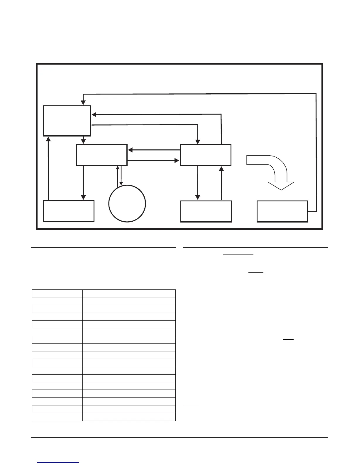
How these modes are linked and how they may be invoked are shown in the sequence diagram below:
MAINTENANCE
REMOTE
MAINTENANCE
SERVICE
MODE
POWER OUT OF
RANGE STATE
Power < 18V
Power > 32V
(Power-ON)
INITIALIZATION
NORMAL
DISPLAY
FAN
SPEED
USB
Disconnected
+ Cover Close
Cover Open +
USB
Connected
RESET +
DISABLE
RESET +
Password Enter
Cover
Open
Cover
Close
RESET + Password Enter (During Auto Speed Procedure)
Maintenance Timeout or after TEST + RESET + DISABLE (When Device Configuration has been Changed)
Maintenance Timeout or after
TEST + RESET + DISABLE
(No Need for Device to Initialize)
Power in Correct Range
Figure 4: FAAST LT device state diagram
FACTORY DEFAULT SETTINGS (‘OUT-OF-THE-BOX’)
A full list of the factory default settings can be found in the Advanced
Set-Up and Control Guide. Some key default settings are detailed
in Table 3 below:
Table 3: Main default settings
FUNCTION FACTORYDEFAULTSETTING
Passcode 3111
Maintenancetime‐out 5min
Disabletime‐out 60min
Alarmlatched Yes
Alarmdelay 0
Fanspeedmode Auto
Referenceflow 45l/min
Hi/Loflowthreshold ±20%
Flowfaultdelay 60s
Filterduedate 2099
Generalfaultlatched No
Generalfaultdelay 60s–stand‐aloneunit;0–loop‐basedunit
Externalinput Normalopen;shortresetsdevice
Pre‐Alarmdelay 0(N/Atoloop‐basedunit)
Alarmlevel 1(N/Atoloop‐basedunit)
Alarmmode Sensor(Loop‐basedversiononly)
CONNECTING TO A PC
A PC connection will only work when the FAAST LT device is in
the Remote Maintenance mode. Always make sure that PipeIQ
is running on the PC and that the FAAST LT unit has been set to
Remote Maintenance mode before connecting the USB cable.
IMPORTANT NOTE: See First time connection below when a new
PC or a new version of PipeIQ is used.
Remote Maintenance mode
To enter the Remote Maintenance mode, rst set the device to
Maintenance mode (see: Password access to Maintenance Mode
section). Then open the detector front door by releasing the two
Phillips screws. Connect a USB cable from the internal socket
in the centre of the device to a spare USB port on the PC; the
detector will now be in the Remote Maintenance mode.
Make sure that the USB connector is pushed fully into the FAAST
LT socket – should feel a click. Check the integrity of the cable
before looking for other connection problems.
The USB connection must be made within 5 minutes of entering
the Maintenance password.
First time connection
The rst time a PC running PipeIQ is connected to a FAAST
LT detector, the USB port drivers will be installed. Follow these
instructions carefully to avoid having to uninstall and reinstall the
PipeIQ software.
Before plugging in the USB cable, ensure that PipeIQ is running
on the PC (an open project is not required), and that the FAAST
LT unit has been set to Maintenance mode. (PipeIQ is available on
the CD-ROM provided with the FAAST LT unit or from www.faast-
detection.com).