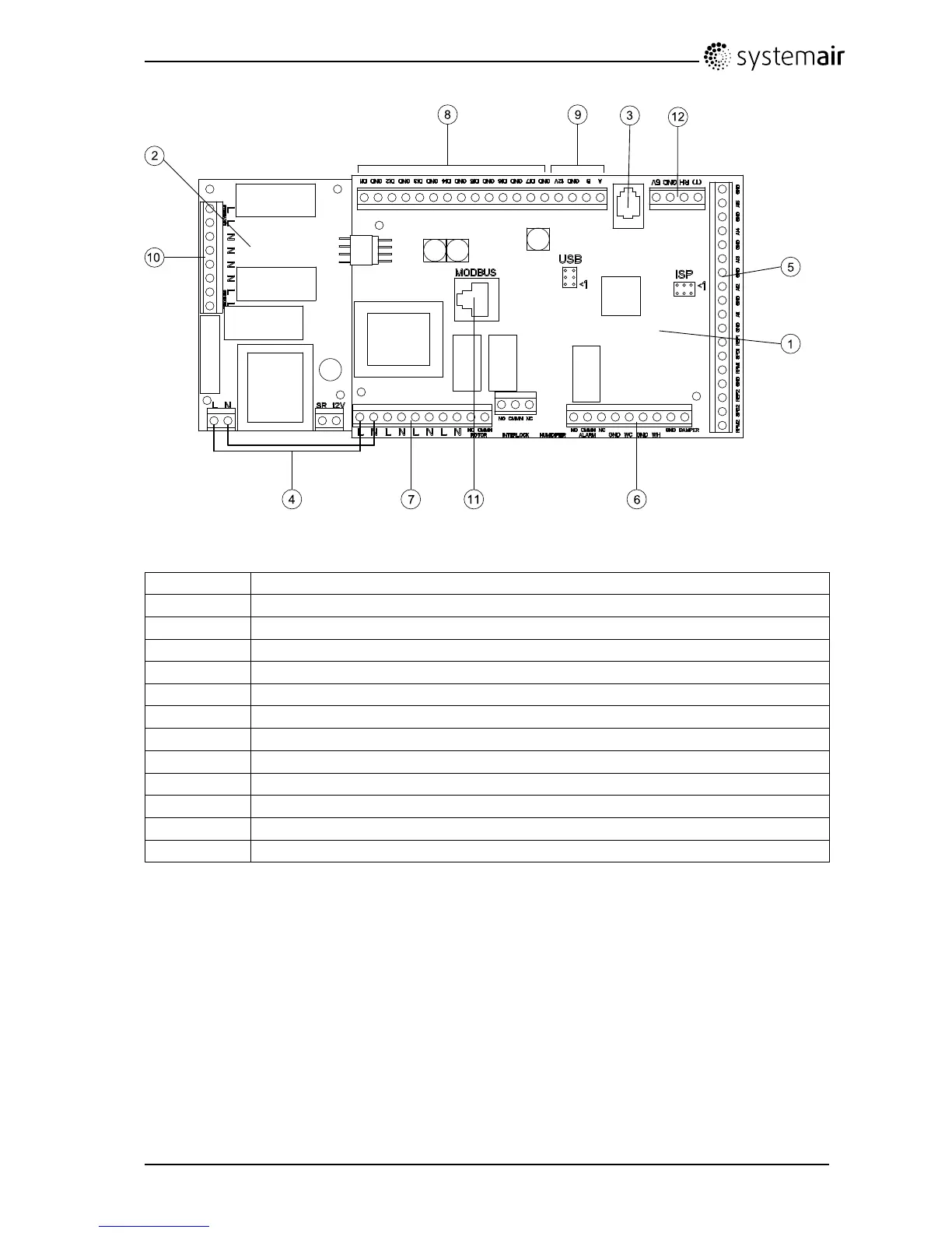
Fig.8Printcard
PositionDescription
1Mainprintcard
2
Printcardforelectricalheater
3
Connectiontoexternalcontrolpanel(connectedtounitcasing)
4Mainssupplyconnectionbetweenmainprintcardandelectricalheaterprintcard
5
TerminalsforAI1–5(tempsensors)andmotorcontrol
6
Terminalsforexternalconnections
7
Terminalsformainssupplyconnections
8
Terminalsfordigitalinputs(DI1–7)
9
Terminalsforinternalcontrolpanel.
10
Terminalsforregulatedpowersupplytoelectricalheater
11
Modbusconnection.See"UsermanualModbus"fordetails.
12
Terminalsforinternalrelativehumiditysensor
7.10.2Externalconnectionsontheprintcard
Connectionterminalsforexternalequipmentcanbefoundonthemainprintcardinsidetheelectrical
connectionbox.
SAVEVTR200/BInstallationandService
208061
18
SystemairSverigeAB

 Loading...