10.3.5Temperaturesensors
Fourtemperaturesensors(NTC,10kΩat25°C)areincludedintheunitfromfactoryandpositionedinthe
correspondingairchambers.
Thesensorsareconnectedtothemainprintcard.Seewiringdiagramformoreinformation.
10.3.6Humiditysensor
Relativehumiditysensor(RHS)isincludedintheunitfromfactoryandpositionedintheextractairchamber.
Thesensorisconnectedtothemainprintcard.Seewiringdiagramformoreinformation.
10.3.7ElectricalRe-heaterbattery
There-heaterbatteryispositionedinthesupplyairchamber.
There-heaterisactivatedbyarelayandswitchesonifthesupplyairtemperatureislowerthantheset
pointandswitchesoffifoneormoreofthefollowingconditionsaremet:
1.Ifthesupplyairtemperatureisabovethesetpoint.
2.Iftheoverheatprotectionisactivatedorthesensorismalfunctioning.
3.Iftheemergencythermostatistriggeredorbroken.
4.Ifthesupplyairsensorisinerrorstate.
5.Ifthesupplyairfanisnotrunning.
6.Iftheheaterissettodisabledinthemenu.
7.Ifre-heaterisdisabledbydigitalinput4(DI4).
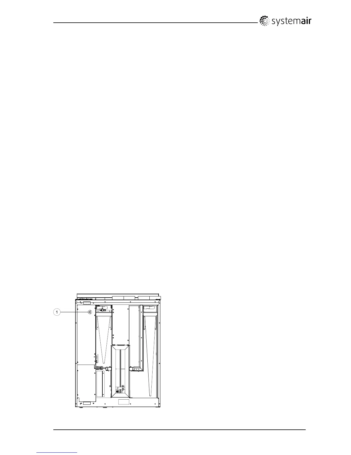
10.3.8Overheatprotectionresetbutton
Ifthesupplyairtemperatureislow,itcanindicatethattheoverheatprotectionistriggered.Theoverheat
protectioncanberesetbypressingtheresetbutton(1).
Fig.11Overheatprotectionresetbutton
SAVEVTR200/BInstallationandService
208061
36
SystemairSverigeAB

 Loading...