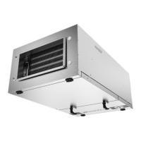
Fig.9Externalconnectionsontheprintcard
PositionDescriptionRemark
1
Outdoor/exhaustairdamperNormallyopen,230V1~,max0,1A/
24VAC1A
2
Outdoor/exhaustairdamperReference
3
Outdoor/exhaustairdamperNormallyclosed,230V1~,max0,1A/
24VAC1A
4
Sumalarm
Normallyopen,24V,max1A
5
SumalarmReference
6
Sumalarm
Normallyclosed,24V,max1A
7
GNDReference
8
Watercoolercontrolsignal(AO2)0–10VDC
9
GNDReference
10
Waterheatercontrolsignal(AO1)0–10VDC
11
GNDReference
12
Bypassdamper/Rotorcontrol(AO3)Ifused,0–10VDC
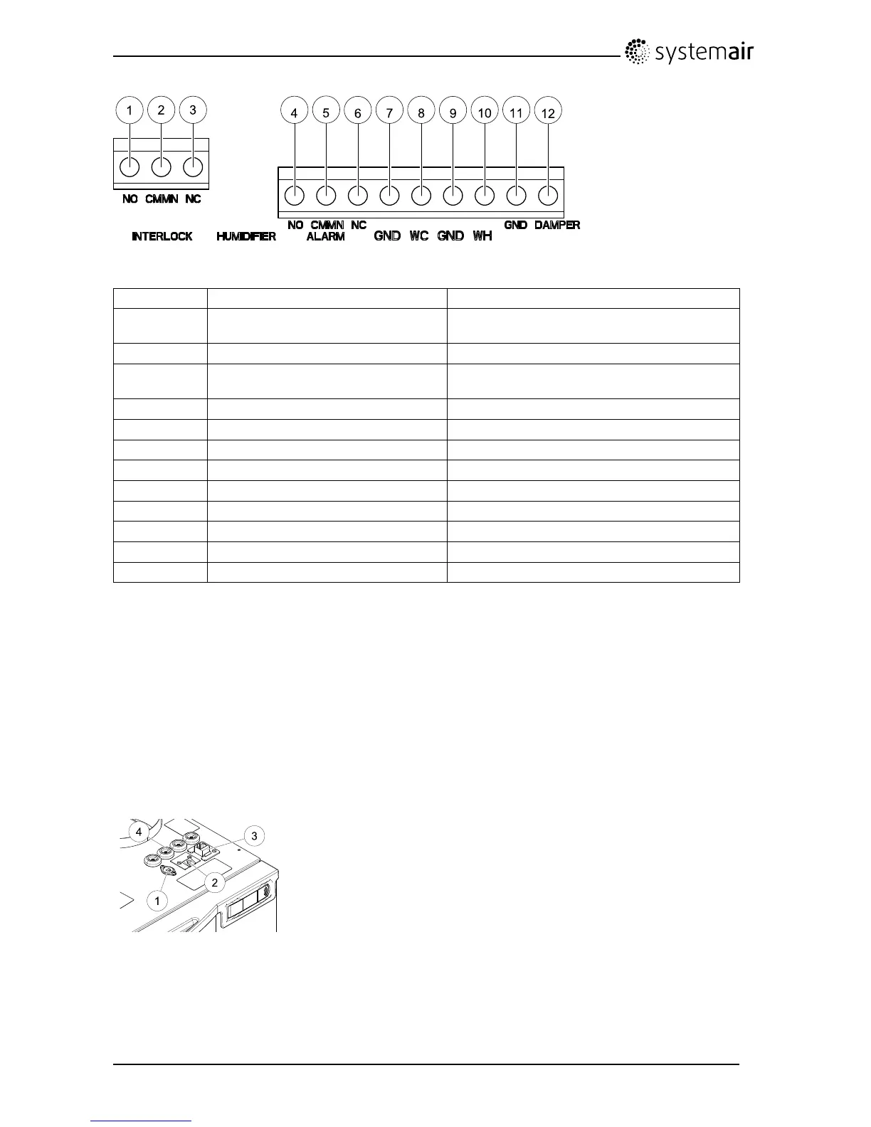
7.11Externalconnectionsontopoftheunit
Twooftheconnectionsonthemainprintcardarewiredtoplugsontheunitcasing:
•connectiontoanexternalcontrolpanelthroughamodularconnector.
Maximumcablelength:50m.
Cabletype:Flat4–conductorCECPhonecable.
•ExternalModbusconnector.
Maximumcablelength:90mincableduct+10minworkingarea.
Cabletype:LANTCPCat5E4x2XAWG24cable.
•connectiontoDI3withpossibilitytocongurethefanspeedsindividuallythroughapotentialfree
on/offswitch
1.ConnectiontoDI3throughanon/offswitch
2.Connectiontocontrolpanel
3.ExternalModbusconnection
4.Cableglands
8Beforestartingthesystem
Whentheinstallationisnished,checkthat:
•Theunitisinstalledinaccordancewiththeinstructions
SAVEVTR200/BInstallationandService
208061
19
SystemairSverigeAB

 Loading...