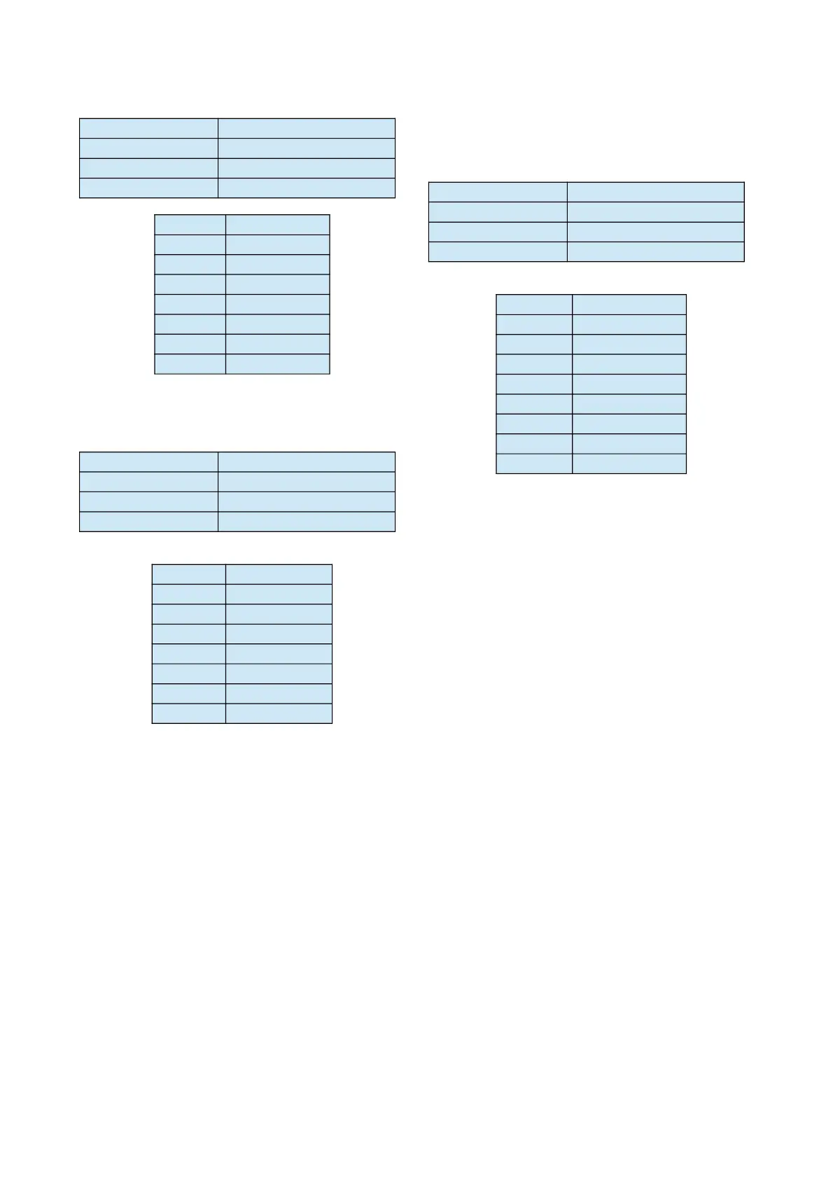
Manager Input Port
Type V.24/RS232 - Fixed DCE
Speed 9600bps (8,n,1)
Signals TXD, RXD, SIG GND
Connector 9-way Dsub Female
PIN SIGNAL
2 RXD (o/p)
3 TXD (i/p)
5 SIG GND
6 Relay 1 COM
7 Relay 1 N/O
8 GND
9 Opto 1 (i/p)
* Opto Input – Trigger by strapping to ground.
Manager Output Port
Type V.24/RS232 - Fixed DTE
Speed 9600bps (8,n,1)
Signals TXD, RXD, SIG GND
Connector 9-way Dsub Female
PIN SIGNAL
2 RXD (i/p)
3 TXD (o/p)
5 SIG GND
6 Relay 2 COM
7 Relay 2 N/O
8 GND
9 Opto 2 (i/p)
* Opto Input – Trigger by strapping to ground.
Auxiliary Data Port
The RS232 terminal interface can support auxiliary
bidirectional transmission of asynchronous data
over the ISDN and X21 network.
Type V.24/RS232 - Fixed DCE
Speed 9600bps (8,n,1)
Signals TXD, RXD, CTS, S GND
Connector 9-way Dsub Female
PIN SIGNAL
1 Alarm N/C
2 AUX RXD (o/p)
3 AUX TXD (i/p)
4 Alarm COM
5 SIG GND
6 Alarm N/O
8 AUX CTS (o/p)
9 Remote Trigger*
NOTE: The CTS output signal should be used for Flow
Control when Auxiliary Data is enabled.
Alarm Signal
The C530ip provides a set of alarm relay contacts
with a minimum of 0.5 second duration. These relay
contacts are provided on the auxiliary data port
connector.
For connection information, please refer to the pin-
out detail of the auxiliary data connector. The
maximum voltage is 50V.
Page 20