DHR/AR Series SALS Accessory Getting Started Guide Page 13
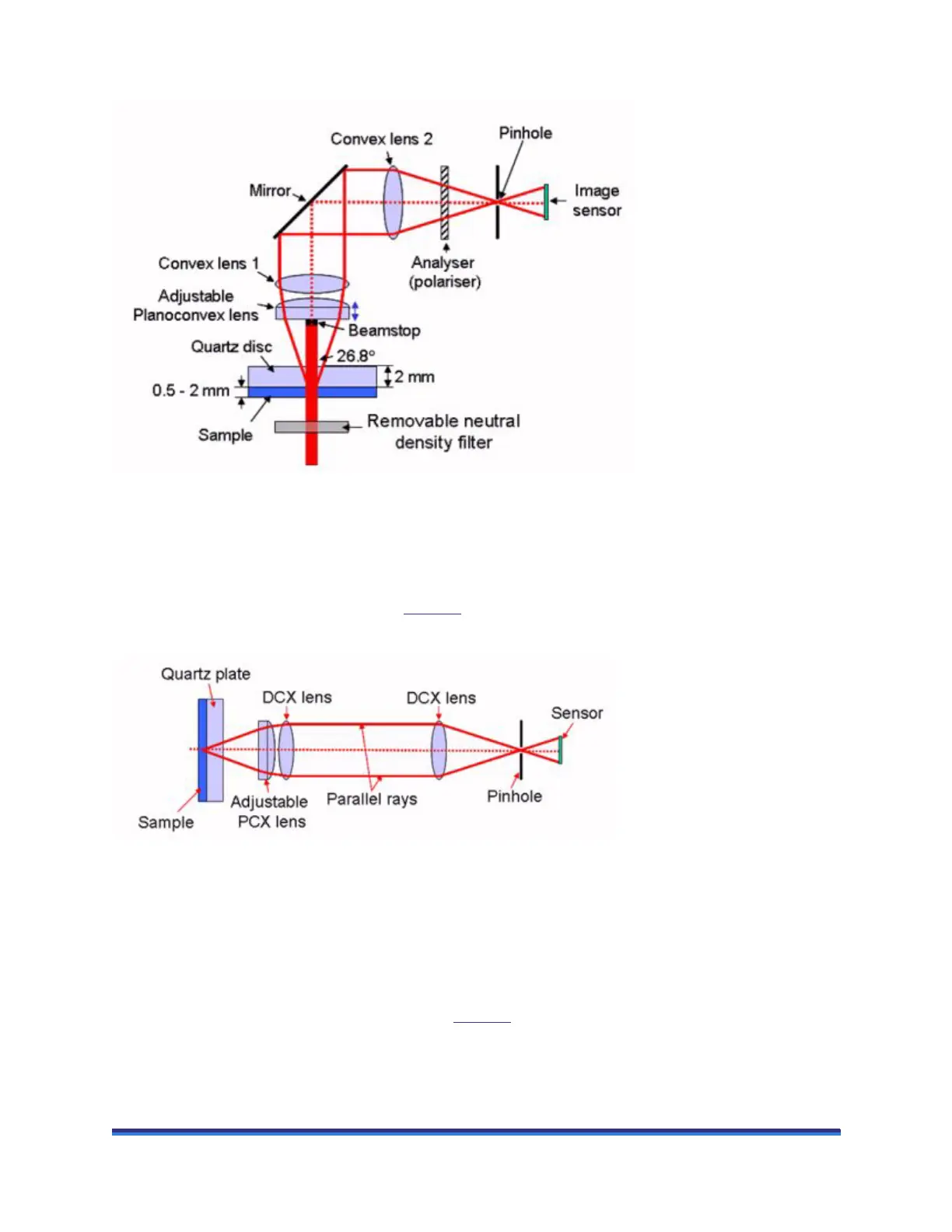
Figure 5 Schematic of TA Instruments SALS optics.
The position of the PCX lens is indicated by the inscribed scale. One rotation of the lens holder is equiva-
lent to a travel distance of 1 mm. The zero position is assumed to be where the DCX and PCX lens are in
contact.
A simplified view of the optics is given in Figure 6
, in which the deflection through 90° is ignored (this
does not affect principle of the optical system).
Figure 6 Simplified view of the SALS optics.
The maximum scattering angle will also depend on the position of the planoconvex lens and the refractive
index of the sample.
Adjusting the Plane of Focus
The position of the planoconvex lens indicated in Figure 6 can be adjusted to alter the image point within
the sample. It is expected that the plane of focus will be at or close to the sample midheight. The position
of the lens that gives this will depend on the refractive index of the sample.
 Loading...