Do you have a question about the TA Instruments ARES-G2 and is the answer not in the manual?
Links to supplemental information for the Getting Started Guide.
Covers regulatory compliance, safety, and EMC standards for the instrument.
Lists essential equipment needed for operating the instrument safely.
Explains the meaning and purpose of various instrument safety symbols.
Safety measures for electrical, chemical, and thermal hazards during operation.
Guidance on safely lifting and moving the ARES-G2 instrument.
Step-by-step instructions for moving the instrument with a cart.
Procedures for moving the instrument manually without a cart.
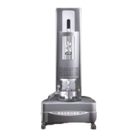
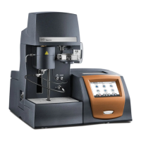
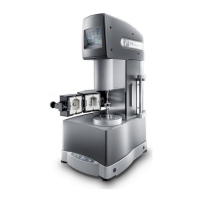
Provides a general description of the ARES-G2 and its system components.
Details the primary components of the ARES-G2 test station.
Explains the stage's operation and functions of the ARES-G2 keypad.
Describes the functions and gauges displayed on the instrument's touch screen.
Displays instrument status, system information, and diagnostics.
Covers status messages, instrument ID, network settings, and calibration functions.
Details the Force Rebalance Transducer used for measuring torque and normal force.
Describes the air bearing motor and the system's modular power supplies.
Information and safety warnings for the Forced Convection Oven accessory.
Details the LN2 cooler and Dewar flask for low-temperature operation.
Details the ACS-3 chiller and Lower Peltier Plate environmental control.
Explains the sealed fluid bath for precise temperature control.
Details camera and solvent trap accessories for the ARES-G2.
Lists the geometries compatible with the ARES-G2.
Provides recommendations for geometry selection based on sample type.
Lists the technical specifications for the ARES-G2.
Instructions for unpacking, repacking, and preparing the ARES-G2 for installation.
Procedures for inspecting the system and selecting a suitable location.
Steps for installing the ARES-G2 and connecting the air dryer system.
Describes various ports on the rear of the ARES-G2 for connections.
Requirements for gas pressure and air quality for optimal performance.
Instructions for purge connections and details of signal panel connectors.
Steps for connecting cables and lines to the instrument.
Procedures for router setup and connecting computer to LAN/Switch.
Steps to connect the main test station power supply unit.
Procedures for locking/unlocking the motor and transducer mechanisms.
Steps to connect the test station power cable.
Instructions for leveling the instrument using its feet.
Procedures for starting up and safely shutting down the ARES-G2 system.
Instructions for completely powering off the instrument for maintenance or relocation.
General outline for performing experiments and setup prerequisites.
Steps to calibrate the instrument for accurate experimental results.
Details calibration methods for torque, normal force, and phase angle checks.
Verifies test station operation and calibration using PDMS reference material.
Guidance on geometry selection, testing limits, and compliance factors.
Defines operational range and basic guidelines for installing geometries.
Steps for installing the upper geometry onto the transducer.
Steps for installing the lower geometry onto the motor mount.
Overview of test types and steps for setting up an experiment.
Steps to set up and run an experiment after geometry installation.
Procedures for cleaning geometries and performing routine maintenance.
Inspection of cables/hoses and maintenance of power supply units.
Instructions for cleaning the instrument exterior and touch screen display.
Guidance on solving problems using TRIOS software online help.
Lists available replacement parts for the ARES-G2.
| Brand | TA Instruments |
|---|---|
| Model | ARES-G2 |
| Category | Measuring Instruments |
| Language | English |