120 Part F: Configuring Channels © Tait Electronics Limited December 2007
If the High pass filter check box is cleared, any DC content present on the input
will also offset the Tx carrier frequency. Even with no input, a small fixed
frequency carrier offset may be noticed. Clearing the check box will mean that
the frequency stability of your system is dependant on the input DC signal
stability, not the internal or external frequency reference accuracy.
Extended bypass When the Bypass check boxes are enabled on both the transmit and the receive
paths, Extended bypass check boxes appear. Extended bypass adds an equaliser
that amplifies higher frequencies to extend the available audio frequencies on
the unbalanced line, providing up to 6 kHz (receive path) or 5.5 kHz (transmit
path). Enabling one Extended bypass check box automatically enables the
other; you cannot configure extended bypass separately for the transmit and
receive paths. Enabling extended bypass makes the balanced line and internal
talk-through repeater connections unavailable; their screen display is therefore
disabled.
The high pass filter is also available for extended bypass.
Extended bypass is necessary for applications such as 9600 baud data in the
GMSK format using external modems. See TN-1114-AN for more details.
Line level The Line level boxes on the transmit path define the level of the line input that
the base station expects. The line level you select affects the gain across the
transmit path.
When the base station receives a line input at the level you select, it transmits
at 60% of the maximum transmit deviation. For channels using the default
profile, the maximum transmit deviation is determined by the channel spacing
(see “Channel Spacing” on page 138). For channels using custom profiles, it is
defined by the parameter Max Tx deviation (see “Max Tx deviation” on
page 109).
Line levels are expressed as dBm for the balanced line input and Vpp (volts
peak-to-peak) for the unbalanced line input.
Tip: To determine the expected line level, set up your system and
use a Service Kit diagnostic test to measure the level. See
“Measuring the Audio Input Level” on page 175.
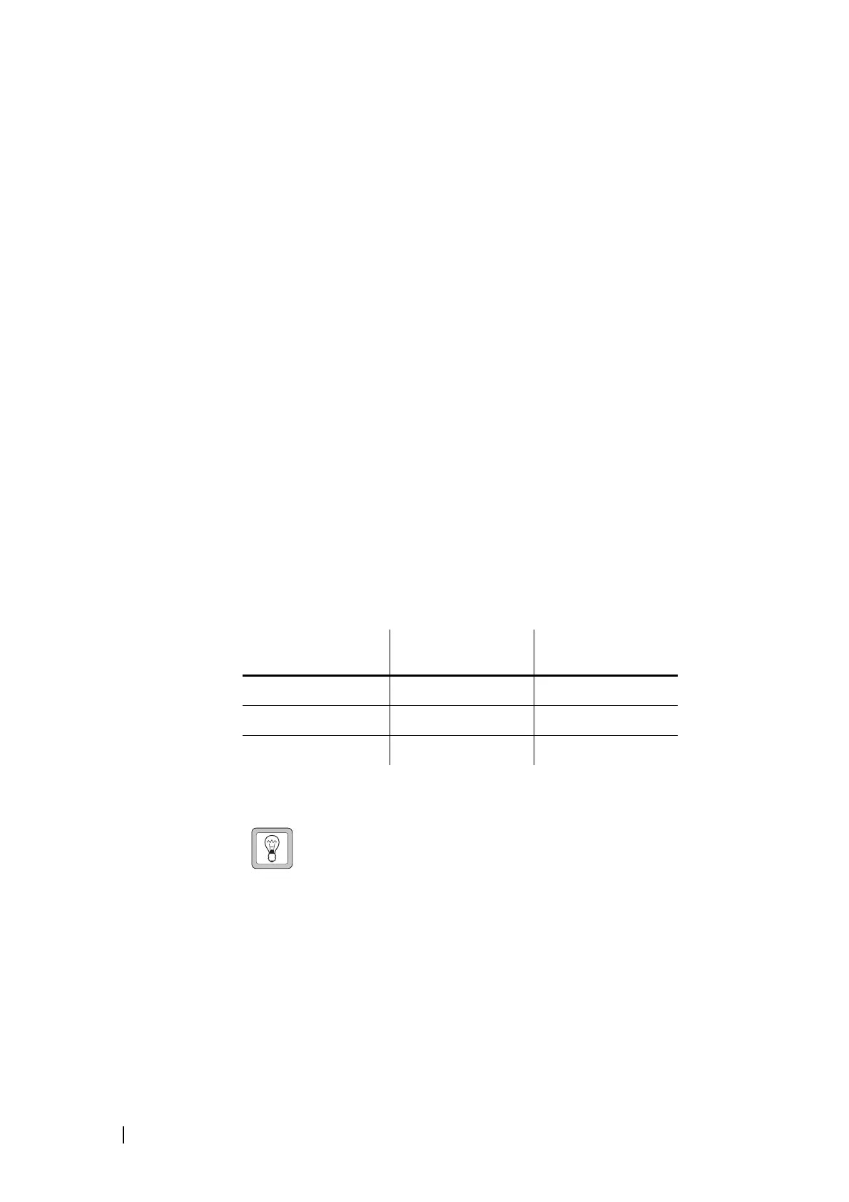
Channel spacing
Equivalent Tx max
deviation (Hz)
60% of Tx max
deviation (Hz)
12.5 kHz Narrow Band 2500 1500
20 kHz Mid Band 4000 2400
25 kHz Wide Band 5000 3000

 Loading...


