58 Network Circuitry TB9100 Reciter Service Manual
© Tait Electronics Limited January 2006
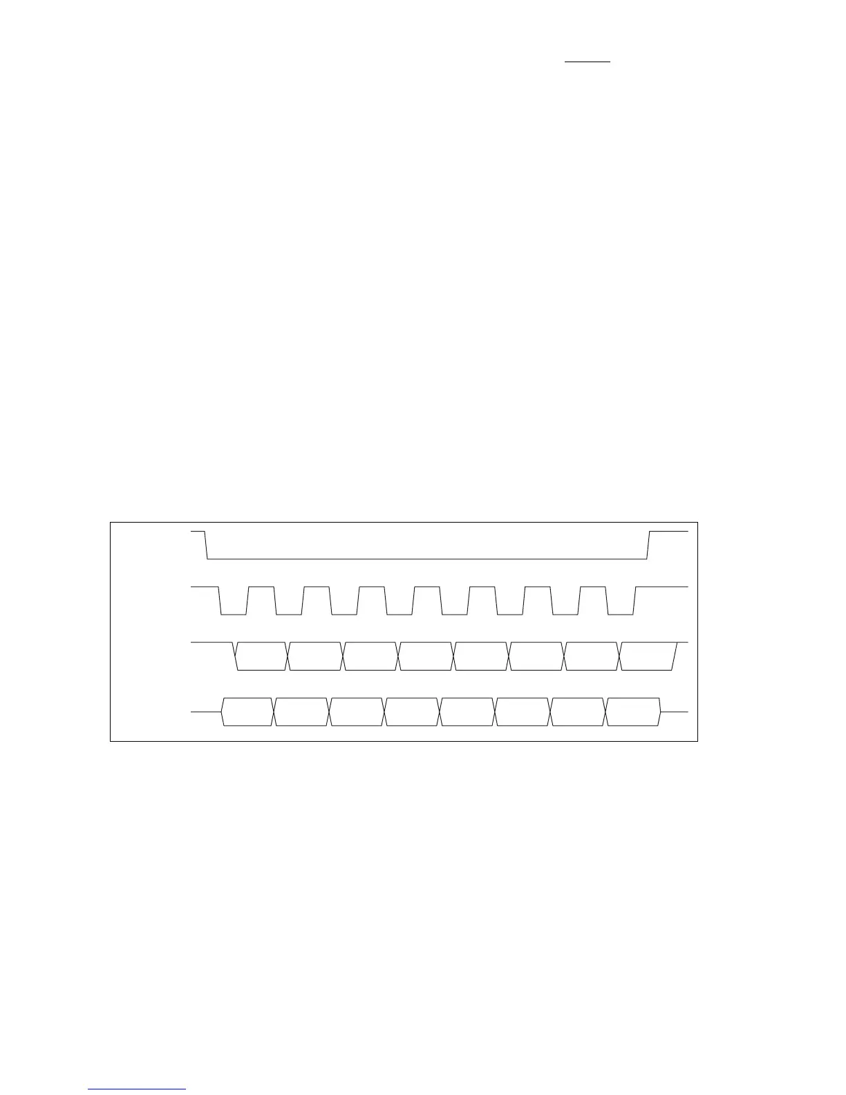
As the server, the RISC SIO generates a select signal (SPISEL) to enable the
MPC’s SPI port for data transfer. The select signal enables multiple client
devices to be connected to an SPI bus, but in the case of the reciter to ASIF
connection, only one client, the MPC SPI port, exists. The reciter RISC
SIO port also generates the shift clock (SPICLK); the data is shifted out on
the negative-going edge of the clock and shifted in on the positive-going
edge.
The clock shifts data in (on the SPIMISO pin) and out (on the SPIMOSI
pin) of a single shift register, ie. as transmitted data is shifted out of the msb
end of the shift register, received data is shifted in to the lsb of the same
register. Since a single register is used for both receive and transmit data, it
is necessary to read the received data before shifting in new data from the
next transfer. The MPC’s SPI port double buffers its SPI shift register to
provide additional timing leeway for the software to recover the received
data. The SIO port on the reciter RISC is not double buffered, so it is a
limiting factor on the achievable transmission rate. The MPC’s SPI port is
capable of variable-length transfers, but the reciter RISC’s SIO port is
restricted to 8-bit transfers.
A typical set of waveforms is shown in Figure 5.6. Refer to chapter 30 of
the MPC866 user’s manual (reference 2) for a more detailed description of
SPI operation.
Inter-IC (I
2
C) Bus The I
2
C bus is used to communicate with two peripheral devices: an
E2PROM (U202) and the CODEC (U500). The E2PROM is used for
storing configuration information related to the ASIF. The CODEC
configuration is also performed via the I
2
C bus (see “CODEC Digital
Interfaces” on page 79). A more detailed description of I
2
C bus operation
may be found in reference 23.
The I
2
C bus consists of two lines, SCL and SDA, which are driven by open-
drain drivers and hence require the pull up resistors, R205 and R216.
The MPC is assigned as the server device and drives the clock line, SCL.
This clock determines the bit rate of the data transfers, which occur bi-
directionally over the data line, SDA. The beginning and end of a message
Figure 5.6 SPI Transfer Waveforms
SPISEL
SPICLK
SPIMISO
msb
lsb
SPIMOSI
msb
lsb

 Loading...


