114 Replacing Modules TB9100/P25 CG/P25 TAG Installation and Operation Manual
© Tait Limited March 2014
Link Settings
A set of links is provided on the interconnect board for each position in the
subrack, as described in Table 7.1 . You can set these links to connect either
the reciter’s alarm or Rx gate status signal to the appropriate channel LED
on the control panel (refer to “Control Panel” on page 79).
There is a link on the control panel board which allows you to select the
color displayed by these LEDs. Refer to “Configuring the Control Panel
Board” on page 99.
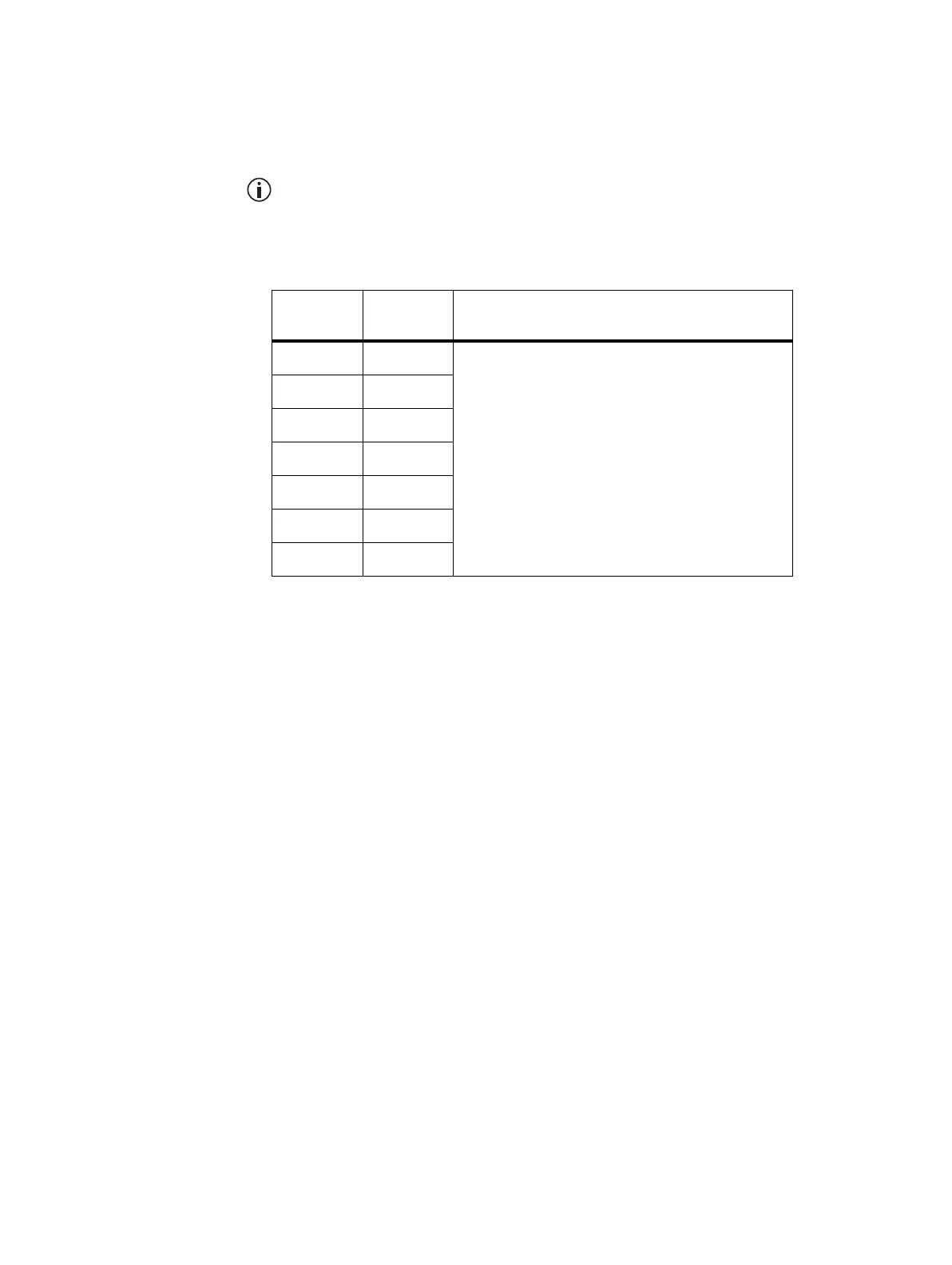
Table 7.1 Link settings for selecting alarm or Rx gate signals
Subrack
Position Link Link Settings
1J16
alarm status signal: link pins 1 & 2
Rx Gate status signal: link pins 2 & 3
2J18
3J19
4J20
5J21
6J22
7J23

 Loading...


