122 TMAA10-02 Handset TM8100/TM8200 Accessories Manual
© Tait Electronics Limited August 2005
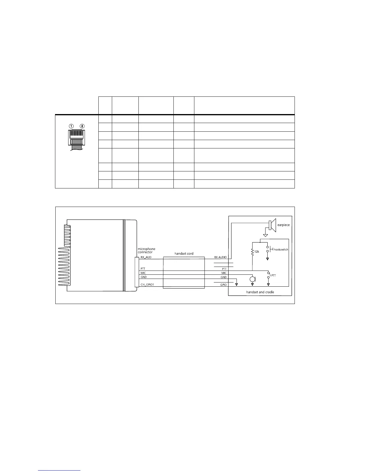
15.3 Interface Specification
The following table and diagram summarizes the signals used for the handset
on the radio’s microphone connector and shows the interface between the
handset and the radio.
.
Table 15.5 Handset microphone connector—pins and signals
Pin Signal
Handset PCB
Connector
Colour Description
1 RX_AUD 8 brown receive audio to handset
2 —— —not connected
3 —— —not connected
4 PTT 2 white PTT and hookswitch
5 MIC 9 yellow audio from the handset to dynamic-mic
support board
6 GND 10 green analogue ground
7 —— —not connected
8 CH_GPIO1 3 blue programmable line controlling private mode
Figure 15.2 Handset to radio interface

 Loading...


