TM8100/TM8200 Accessories Manual TMAA01-01 Line-Interface Board 19
© Tait Electronics Limited August 2005
Setting the Line
Output Level (RV2)
Monitor the line output (SK1 pins 14 and 15) and apply an on-channel
signal from the RF signal generator at an output level of -47dBm,
modulated to 60% of system deviation, at 1kHz AF.
Adjust the RV2 for a line output level of -10dBm.
Setting the Line
Input Level (RV3)
Apply a line input signal of -10dBm and key the transmitter.
■ For a two-wire configuration, apply the line input signal to pins 14 and
15 on SK1.
■ For a four-wire configuration, apply the line input signal to pins 4 and
10 on SK1.
Adjust RV3 until 60% of system deviation at 1kHz is achieved.
2.3 Installing the Line-Interface Board
Note The line-interface board link options must be set before the board
is installed in the radio, as the top side of the line-interface board
is not accessible once the board is screwed to the radio lid.
2.3.1 Parts Required
The following table describes the parts required to install a line-interface
board in a radio. The parts marked with an asterisk (
*
) are not shown in
Figure 2.2 and are used to connect to the radio’s external options connector.
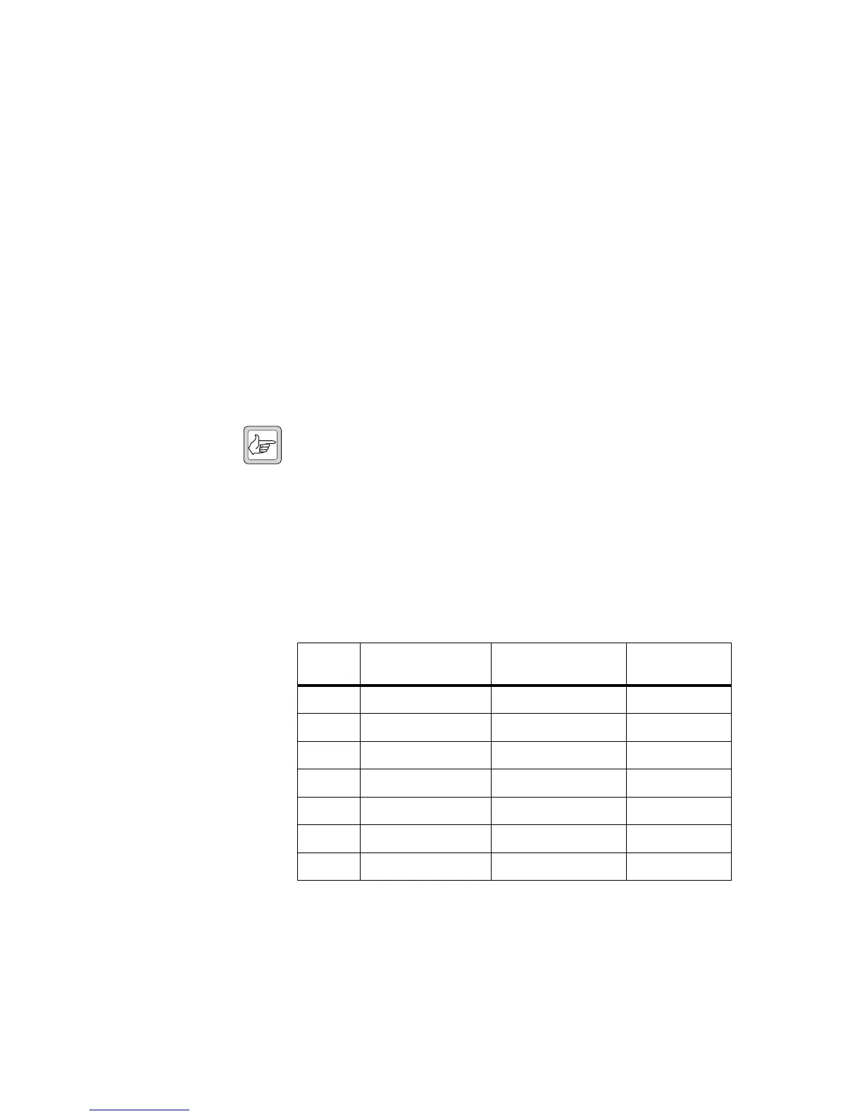
Table 2.5 Line-interface installation parts required
Quantity Internal Part Number Description
Figure 2.2
Reference
1 362-01111-XX
a
a. Contact Technical Support for the exact IPN.
foam seal
d
1 362-01108-XX
a
cover seal
1!
2 347-00011-00 4-40x3/16 screws
1@
2 354-01043-00 screw-lock fasteners h
6 349-02062-00 M3x8 screws j
*
1 240-00010-80 D-range plug —
*
1 240-06010-29 D-range hood —
 Loading...