TM8100/TM8200 Accessories Manual TMAA01-05 Options-Extender Board 45
© Tait Electronics Limited August 2005
4.2 Installing the Options-Extender Board
4.2.1 Parts Required
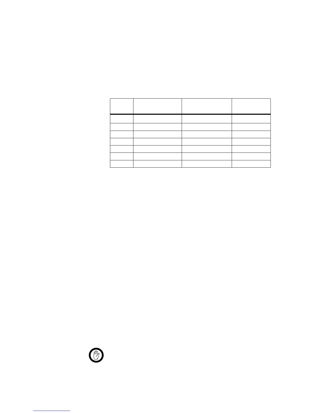
The following table describes the parts required to install an options-extender
board in a radio. The parts marked with an asterisk (
*
) are not shown in
Figure 4.2 and are used to connect to the radio’s external options connector.
4.2.2 Installation Procedure
1. Disassemble the radio in order to gain access to the options cavity.
For detailed disassembly instructions, refer to the disassembly proce-
dure in the service manual.
Refer to the diagram on the following page and the instructions below.
2. Remove the top cover and lid
b
from the radio to access the
options cavity.
3. Remove the external options connector bung
c
, if it is fitted.
4. On the inside of the radio lid place the foam seal
d
over the external
options connector cavity
e
.
5. With the top side of the options-extender board
f
facing the radio
lid, guide the external options connector
g
(the D-range connector
on the options-extender board) into the external options connector
cavity.
6. Screw the external options connector to the radio lid using the two
screw-lock fasteners
h
.
Tighten the fasteners
to a torque of 0.9N·m (8lbf·in).
Important The external options connector screw-lock fasteners must
be tightened correctly before screwing the options-
extender board onto the mounting posts
i
.
Table 4.2 Options-extender installation parts required
Quantity Internal Part Number Description
Figure 4.2
Reference
1 362-01111-XX
a
a. Contact Technical Support for the exact IPN.
foam seal
d
1 362-01108-XX
a
cover seal
1!
2 347-00011-00 4-40x3/16 screws
1@
2 354-01043-00 screw-lock fasteners h
4 349-02062-00 M3x8 screws j
*
1 240-00010-80 D-range plug —
*
1 240-06010-29 D-range hood —
 Loading...