TM8100/TM8200 Accessories Manual Installing an Enhanced Remote Kit 99
© Tait Electronics Limited August 2005
11.3.2 Disassembling the Control-Head Interface
Disassemble only as much as necessary to replace the defective parts or to
swap the Micromatch connector loom. Re-assembly is carried out in reverse
order of disassembly.
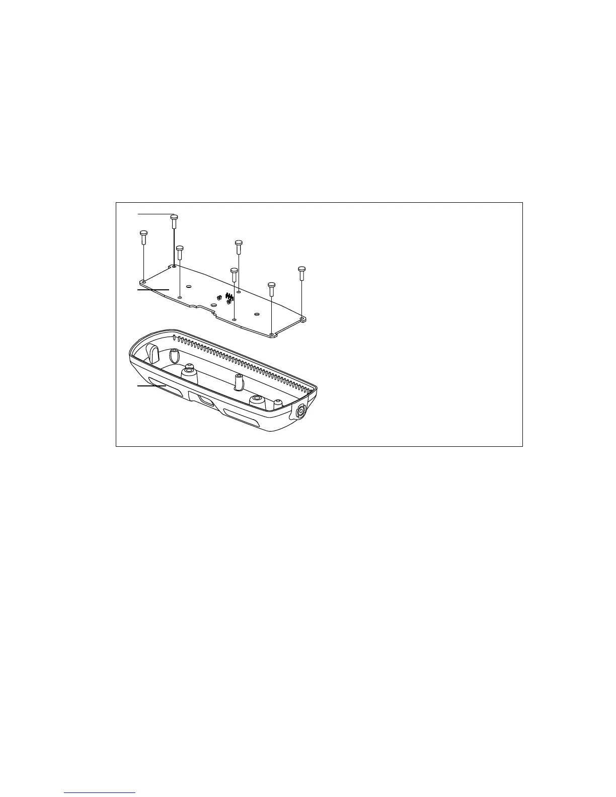
1. Unscrew the seven PT type screws
B and remove the PCB C.
2. Remove the control-head interface loom (not illustrated).
Figure 11.5 Parts of the control-head interface
Description IPN
B 3 x 8 PT screw (x7) 346-10030-XX
a
C control-head interface PCB
D control-head interface 316-06842-XX
a
control-head interface loom219-02914-XX
a
a
Contact Technical Support for the exact IPN.
D
x7
B
C
 Loading...