16 TMAA01-01 Line-Interface Board TM8100/TM8200 Accessories Manual
© Tait Electronics Limited August 2005
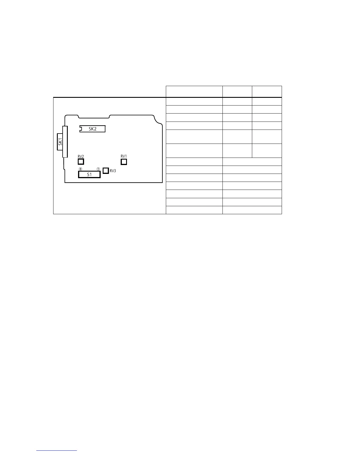
2.2.1 Adjustment Points on the Line-Interface Board
The following table describes the line-interface adjustment points.
Adjustments are made by setting the DIP switches on S1 to either “on” or
“off” and by three variable resistors (RV1, RV2 and RV3).
2.2.2 Test Equipment Setup
The following diagram shows the setup of the test equipment used when
a d j u s t i n g RV 1 , RV 2 a n d RV 3 .
Table 2.1 Line-interface board adjustment points
Function Selection 1 Selection 2
two-wire audio interface DIP1 on DIP2 off
four-wire audio interface DIP1 off DIP2 on
busy/gate = busy DIP3 on DIP4 off
busy/gate = rx-gate DIP3 off DIP4 on
busy/gate logic (active
high)
DIP5 on DIP6 off
busy/gate logic (active
low)
DIP5 off DIP6 on
bi-directional keying line DIP7 on
two-wire keying DIP 7 off
enable gate/keying delay DIP8 on
gate/keying delay adjust RV1
audio line out level adjust RV2
audio line in level adjust RV3
time delay range W1 open
line-interface board
top side

 Loading...


