94 Installing an Enhanced Remote Kit TM8100/TM8200 Accessories Manual
© Tait Electronics Limited August 2005
11.1.5 Mounting the Remote U-Bracket
The remote U-bracket with its self-drilling screws, is used to install the remote
control-head assembly on the dashboard or on any sufficiently flat surface.
Caution When drilling holes in the vehicle, check that drilling
at the selected points will not damage existing wiring.
Important Check that the remote U-bracket is not distorted when the
screws are tightened.
1. Drill any holes required for cables and install suitable grommets or
bushings in the holes.
2. If precise positioning is required, predrill 3mm (1/8 inch) pilot
holes for the self-drilling screws. Reduce the hole size in metal that
is less than 1mm (1/32 inch) thick.
3. Screw the remote U-bracket in the chosen mounting position using the
self-drilling screws provided. Use all four screws provided.
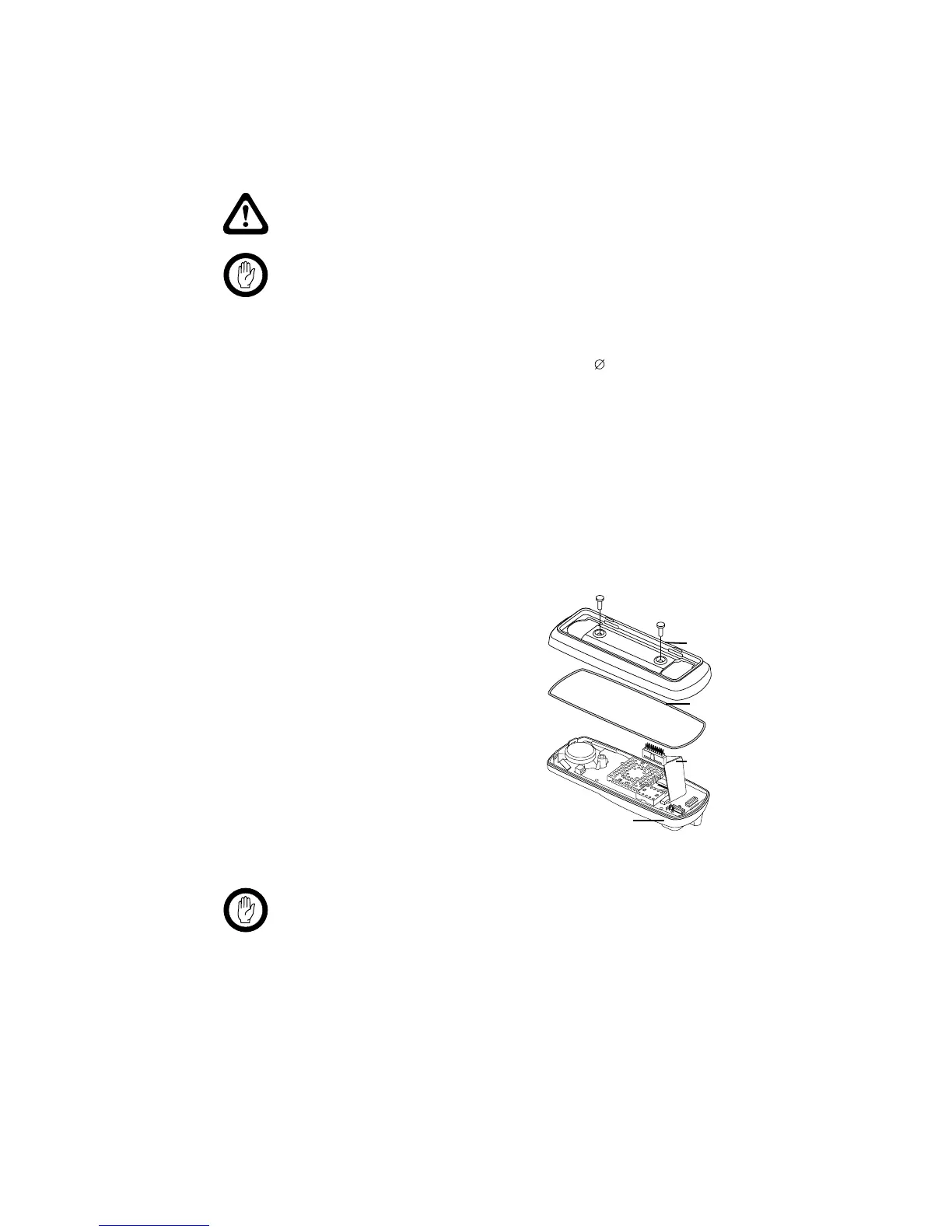
11.1.6 Installing the Control-Head Interface
With the control head separated from the radio body, the control-head
interface
c
must be installed on the rear of the control head.
1. Undo the two Torx T-20 screws
on the adaptor flange of the
control head, and remove the
adaptor flange.
2. Unplug the control-head loom.
The adaptor flange and control-
head loom are not used for the
remote control-head installation.
Keep the two screws for step (4).
3. Plug the control-head interface
loom
i
into the connector on
the control head.
Important When fitting the control-head interface to the control-
head, be careful not to damage the space-frame seal.
4. Use the two screws from step (2) to fit the control-head interface to
the control head through the two screw holes at the rear of the
control-head interface.
Changing the
Remote U-Bracket
Orientation
The control-head interface is configured for installation with the RJ45
socket facing downwards (U-bracket below control head, as in Figure 11.1).
If the RJ45 socket is required to face upwards (control head hanging from
adaptor flange
control head loom
control head
space-frame seal

 Loading...


