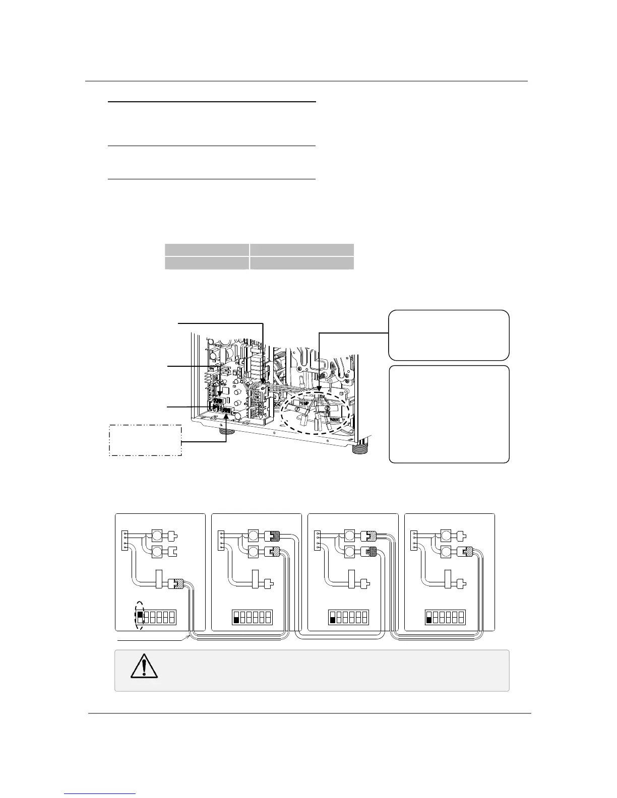
4. Between the “PARENT” and the “CHILD-1” units
Connect the “PARENT” connector of the “PARENT” unit to the “[1]” connector of the “CHILD-1”
unit.
5. Between the “CHILD-1” and the “CHILD-2” units
Connect the “[2]” connector of the “CHILD-1” unit to the “[1]” connector of the “CHILD-2” unit.
6. Between the “CHILD-2” and the “CHILD-3” units
Connect the “[2]” connector of the “CHILD-2” unit to the “[1]” connector of the “CHILD-3” unit.
7. Make sure the 7-seg. LED of all the units’ computer boards display the unit #. The numbering
system automatically allocates the unit # to each water heater in the Easy-Link system, in
accordance with the table below.
P A R E N T
1 2
3
4 5 6
Communication cable
Co nn e c to rs
Right bank of Dipswitches
OFF
ON
OFF
ON
OFF
ON
OFF
ON
11
11
11
11
22
22
22
22
P A R E N T
P A R E N T
P A R E N T
1 2
3
4 5 6
Right bank of Dipswitches
1 2
3
4 5 6
Right bank of Dipswitches
1 2
3
4 5 6
Right bank of Dipswitches
Co nn e c to rs Co nn e c to rs Co nn e ct or s
 Loading...


