MACHINE CONFIGURATION
UPPER FRAME
III-19 TB53FR
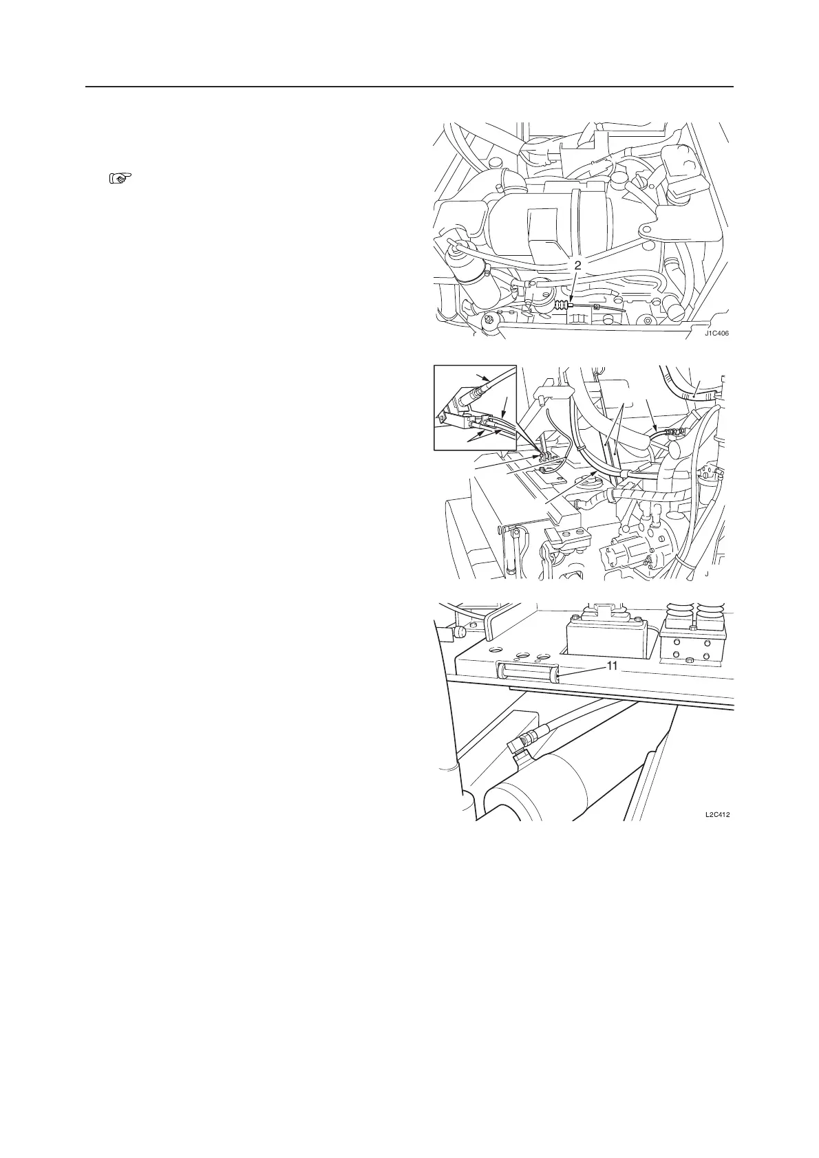
Removing the Floor Frame
1. Disconnect the battery ground cable (1).
2. Remove the cab.
“Removing the Cab”
3. Disconnect the accelerator wire (2) on the engine
side.
• After disconnecting the wire end from the wire
stopper, loosen the fastening nut and take it out
of the bracket.
4. Tilt up the floor and engage the safety stopper (3).
5. Disconnect the hydraulic hoses (4), connected to
the right and left pilot valves, on the side of the
control valves.
• For reassembling, be sure to attach the identi-
fication labels to individual hydraulic hoses.
6. Disconnect the two control cables (5) connected
to the travel levers.
7. Disconnect the electric wiring (6) for travel speed
switching.
8. Disconnect the hydraulic hose (7) connected to
the lock cylinder.
9. Disconnect the electric wirings (8) and (9), con-
nected to the right and left lever stands, on the side
of the engine.
10. Suspend the floor frame temporarily and remove
the three stay dampers (10).
11. Disengage the safety stopper (3) and lower the
floor frame.
12. Remove the bolt and the shaft (11).
13. Suspend the floor frame and remove it.
Installing the Floor Frame
Follow the procedure used for removal in reverse
order.
11
L2C412
J1C406
2
J1C407
9
10
4
8
1
3
5
7
6