15
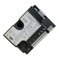
K580M
10 - 12 PHOTOCELLS
opening in order to allow the obstacle to be removed (if dip switch
IN SERIES.
Note: the photocell transmitter must always be supplied by
terminals no. 13 - 15, since the safety system test (photo-
test) is carried out on it. To override the testing of the safety
system, or when the photocells are not used, set dip-switch
no. 6 to OFF. If the photo-test is not successful, the control
unit will not operate.
13 - 14
RX
PHOTOCELLS
13 - 15
TX
PHOTOCELL
16 - 17
GATE OPEN
LED
18 - 19
2
nd
RADIO
CHANNEL
Warning: to connect other devices to the 2nd Radio Channel
(area lighting, pumps, etc.), use an additional auxiliary relay.
20 - 21 AERIAL
M1
LIMIT
SWITCH
(CLS),
(OLS)(COM)
M2 ENCODER
(GND),
(+5V)(ENC)
FS1 - FS2 CAPACITOR
M3
230V AC
MOTOR
(M-COM) (M-CL)
(M-OP).
LOGIC ADJUSTMENTS
TRIMMER
FR.
Turning the
trimmer clockwise (+) increases the motor torque, turning it anticlockwise (-) re-
duces it.
SENS Adjustable only with ENCODER enabled (DIP 11 ON).
Note: by rotating the TRIMMER FR. clockwise the sensitivity to obstacles of the
operaor decreases vice-versa, by rotating it
anti-clockwise, the sensitivity to obstacles of the operator increases and therefore
the thrust force decreases.
WARNING: with the trimmer at maximum, the obstacle detection is disabled!!
T.C.A.
Dip switch
1
AUTOMATIC
CLOSING
On
after opening, the gate automatically closes when the delay set on the
Off automatic closing disabled.
ENGLISH