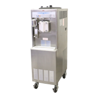
OPERATOR PARTS IDENTIFICATION
4-3
Mod
els 441 & 444
Operator Parts Identification
4
Models 441 and 444 Door Assembly
Figure 4-3
Item Description Part No.
1 Seal- Drive Shaft 032560
2 Shaft- Beater 0086031
3 Beater A. -7 QT. - 1 Pin Support X46233
4 Bearing- Front 013116
5 Gasket- Door -
5.177 ID X 5.9380
016672
6 Decal- Lift Plate Front 015200
Item Description Part No.
7 Valve A.- Draw X13624 - SP
8 O-Ring 1 - 1/16 OD X .139 W-STL 084545
9 Door A.- 1 Spout 7 QT. X30272 - SER
9a Baffle A. - 19” X30274
10 Nut- Stud 021508
11 Blade- Scraper- Plastic 9-13-16L 084950

 Loading...