Section 5
5-1
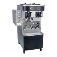
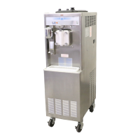
Models 441 & 444
User Interface
5
User Interface
Indicator Light—MIX LOW
The Models 441 and 444 are equipped with a MIX LOW
light located on the front of the machine. When the light
begins to flash, it indicates that the mix hopper has a low
supply of mix and should be refilled as soon as possible.
Always maintain at least 3 in. (76 mm) of mix in the
hopper to allow the mix feed assembly to operate
properly. If you neglect to add mix when the light begins
to flash, a freeze-up may occur, causing eventual
damage to the beater, blades, drive shaft, and freezer
door.
Figure 5-1
Symbol Definitions
The following chart identifies the symbol definitions used
on the operator switches.
= The WASH position.
= The OFF position.
= The ON/AUTO position.
Control Switch
The center position is OFF. The right position is AUTO,
which activates the beater motor and the refrigeration
system. The left position is WASH, which activates the
beater motor only.
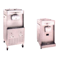
Figure 5-2
Reset Button
On the Models 441 and 444, the reset button is located
on the lower front panel.
The reset button protects the be
ater motor from an
overload condition. If an overload occurs, the reset
mechanism will trip. To properly reset the freezer, place
the control switch in the OFF position. Press the reset
button firmly. Place the control switch in the WASH
position and observe the freezer’s performance. Once
satisfied, place the control switch back in the AUTO
position.
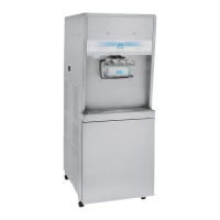
Figure 5-3
 Loading...