1-2
TO THE INSTALLER
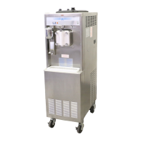
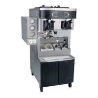
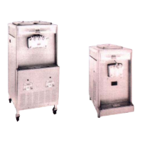
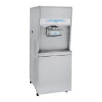
Models 441 & 444
To the Installer
1
Air-Cooled Units
Do not obstruct air intake and discharge openings
Air-cooled units require a minimum of 3 in
. (76 mm) of
clearance around all sides of the freezer to allow for
adequate air flow across the condensers. Install the
deflector provided to prevent recirculation of warm air.
Failure to allow adequate clearance can reduce the
refrigeration capacity of the freezer and possibly cause
permanent damage to the compressor.
Water Connections
(Water-Cooled Units Only)
An adequate cold water supply must be provided with a
hand shut-off v
alve. On the underside rear of the base
pan, two 3/8 in. I.P.S. (for single head units) or two 1/2 in.
I.P.S. (for double head units) water connecti
ons for inlet
and outlet have been provided for easy hookup. 1/2 in.
inside diameter water lines should be connected to the
machine. (Flexible lines are recommended, if local codes
permit.) Depending on local water conditions, it may be
advisable to install a water strainer to prevent foreign
substances from clogging the automatic water valve.
There will be only one water in and one water out
connection for both single head and double head units.
Do not install a hand shutoff valve on the water out line.
Water should always flow in this order: first, through the
automatic water valve; second, through the condenser;
and third, through the outlet fitting to an open trap drain.
IMPORTANT! A
b
ackflow prevention device is
required on the incoming water connection side. Please
see the
applicable national, state, and local codes for
determining the proper configuration.
Electrical Connections
In the United States, this unit is intended to be installed in
accordance with the current edition of the National
Electrical Code (NEC), ANSI/NFPA 70-1987, which
governs the installation of the unit at the local
governmental level.
The purpose of the NEC code is the practical
safeg
ua
rding of persons and property from hazards
arising from the use of electricity. This code contains
provisions considered necessary for safety.
In all other areas of the world, the unit should be installed
in a
ccorda
nce with the existing local codes. Please
contact your local authorities.
Each unit requires one power supply for each data label
on
t
he unit. Check the data label(s) on the unit for branch
circuit overcurrent protection or fuse, circuit ampacity,
and other electrical specifications. Refer to the wiring
diagram provided inside the electrical box for proper
power connections.
WARNING! This equipment must be properly
grounded. Failure to do so can r
esult in severe personal
injury from electrical shock.
IMPORTANT! An equipotential grounding lug is
provided with this unit. Some coun
tries require the
grounding lug to be properly attached to the rear of the
frame by the authorized installer. The installation location
is marked by the equipotential bonding symbol (5021 of
IEC 60417-1) on both the removable panel and the unit's
frame.
IMP
ORTANT!
• Stationary appliances which are not equipped
with a power cord and a plug or another device
to disconnect the appliance from the power
source must have an all-pole disconnecting
device with a contact gap of at least 0.125 in. (3
mm) installed in the external installation.
• Appliances that are permanently connected to
fixed wiring and for which leakage currents may
exceed 10 mA, particularly when disconnected
or not used for long periods, or during initial
installation, shall have protective devices to
protect against the leakage of current, such as a
GFI, installed by the authorized personnel to the
FOLLOW YOUR LOCAL ELECTRICAL CODES.
 Loading...