OPERATING PROCEDURES
6-5
Model C722
Operating Procedures
6
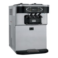
20. Position each draw handle with the adjustment screw
facing down. Slide the fork of each draw handle into
the slot of each draw valve, starting from the right.
Figure 6-16
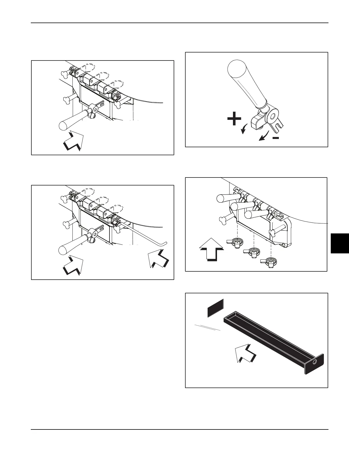
21. Slide the pivot pin through the draw handles as the
handles are inserted into the draw valves.
Figure 6-17
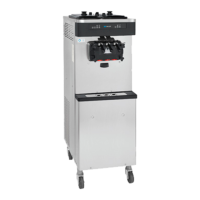
Note: This freezer features three adjustable draw
handles to provide portion control, giving a better
consistent quality to your product and controlling
costs. The draw handle should be adjusted to provide
a flow rate of 5 oz. to 7-1/2 oz. (148 ml to 222 ml)) of
product by weight per 10 seconds.
To increase the flow rate, tighten the screw. To
decrease the flow rate, loosen the screw.
Figure 6-18
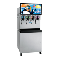
22. Snap the design caps over the bottom of the door
spouts.
Figure 6-19
23. Slide the drip pan into the hole in the front panel.
Figure 6-20