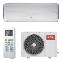
3) Discharged gas state (the state at compressor outlet or condenser inlet) : An adiabatic change is almost
seen in compressor, so the state of discharged gas follows the isentropic line at point B of Figure 7.4.
Accordingly the state point of discharge gas is the intersection with wet-vapor pressure 18.1 kg/cm
2
abs entro-
phy 1.138kcal/kg °K at condensation temperature 46°C, and is a point of pressure 18.1kg/cm
2
abs, temperature
75°C, enthalpy 158.0 Kcal/kg, specific volume 0.00152m
3
/kg, entropy 1.182 Kcal/kg °K, and superheat 30°C.
(Figure 7.4)
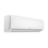
4) State of condensed liquid : The temperature of refrigerant liquid just before expansion valve in the design con-
dition is 40°C, so the state point is the intersection between 46°C wet air pressure 18.1kg/cm
2
abs and 40°C
isothermic line (point C of Figure 7.5) in pressure 18.1kg/cm2 abs, temperature 40°C, enthalpy 112.0 Kcal/kg,
supercooling 6°C.
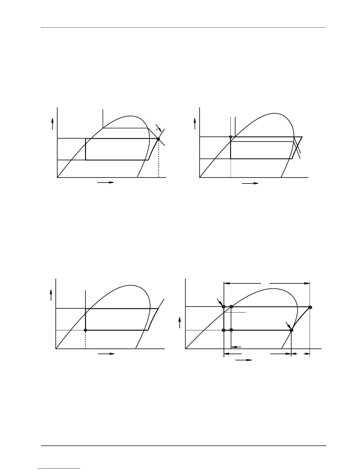
5) State of expansion valve outlet (The state of evaporator inlet) : The state is changed on isentropic line with-
out thermal input/output in expansion valve, so the state point is the intersection between enthalpy 112.0
Kcal/kg line and evaporation temperature 8°C isothermal line (point D of Figure 7.6) at pressure 6.54kg/cm
2
abs, temperature 8°C, enthalpy 112.0 Kcal/kg, specific volume 1.0080m
2
/kg, entrophy 1.025 Kcal/kg °K, and the
degree of dryness 0.2.
Figure 7.4 A state of discharge gas
Figure 7.5 A state of condensed liquid
Figure 7.6 A state of expansion valve outlet
Figure 7.7 A standard refrigerating cycle
 Loading...