Page 16 MICROgarde controller I and II 04.20.11.18
MICROgarde units with integrated PoE
These controllers have a 3A PoE module fitted which offers integrated battery charging with deep
discharge protection. The table below lists output currents from each of the different input classes
available:
Ref Class Output
PoE++ PoE 802.3bt 13.8Vdc, 3A
PoE+ PoE 802.3at 13.8Vdc, 1A
Although the module will operate from 802.3af source equipment this will provide insufficient
current for the controller and readers, it is recommended that 802.3bt is used as standard. When
installing the system observe the manufactures instructions for the source PSE equipment.
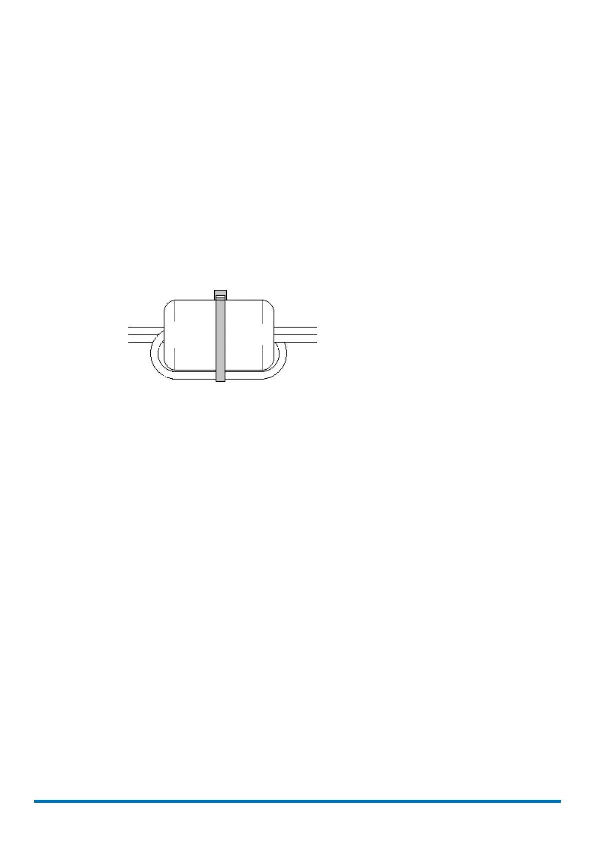
In the event of loss of the PoE source the green LED will turn off, if the system is connected to a
backup battery power will continue to be delivered from this. When installing the controller with an
SLA back-up battery the ferrite supplied should be fitted to the red and black leads with a single
turn, and secured with a cable tie:
The PoE module has no serviceable parts.