114-94438 REV C1
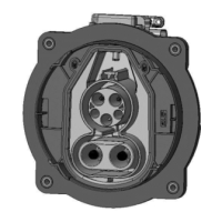
Crimp the conductors to the PIN DIA8.0 CONTACT [Pos. 12] with the specified tools. Care shall be
taken that all braids are caught in the crimp. Not inserted braids may jeopardize HV requirements! Wires
shall be completely inserted to be visible through the inspection hole (Figure 31).
Crimp height H shall be conform to dimension acc. table 1.
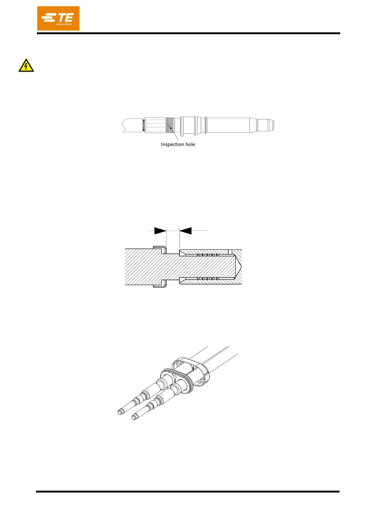
Take care to distance between OUTER FERRULE [Pos. 16] and Pin contact [Pos. 12] as shown
in figure 32.
ATTENTION:
Any damage of the wire isolation must to be avoided!