114-94438 REV C1
Step 5c
DC-HV-Cables of 50mm² in combination with CABLE EXIT AC 20° DOWN (STRAIGHT)
THE SINGLE BRAIDS MAY NOT BE CUT OR DAMAGED DURING DISMANTLE PROCESS.
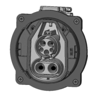
Remove outer isolation and shielding braid of DC-HV-Cable acc. dimension B, remove inner isolation
acc. dimension A (figure 34).
Removal of insulation
"A"
Removal of outer
insulation
“B”
Position outer end
of COVER [POS.10]
“C”
Table 11
Take care, to protect single conductors and braid against contamination, bending and other damages
until crimping process.
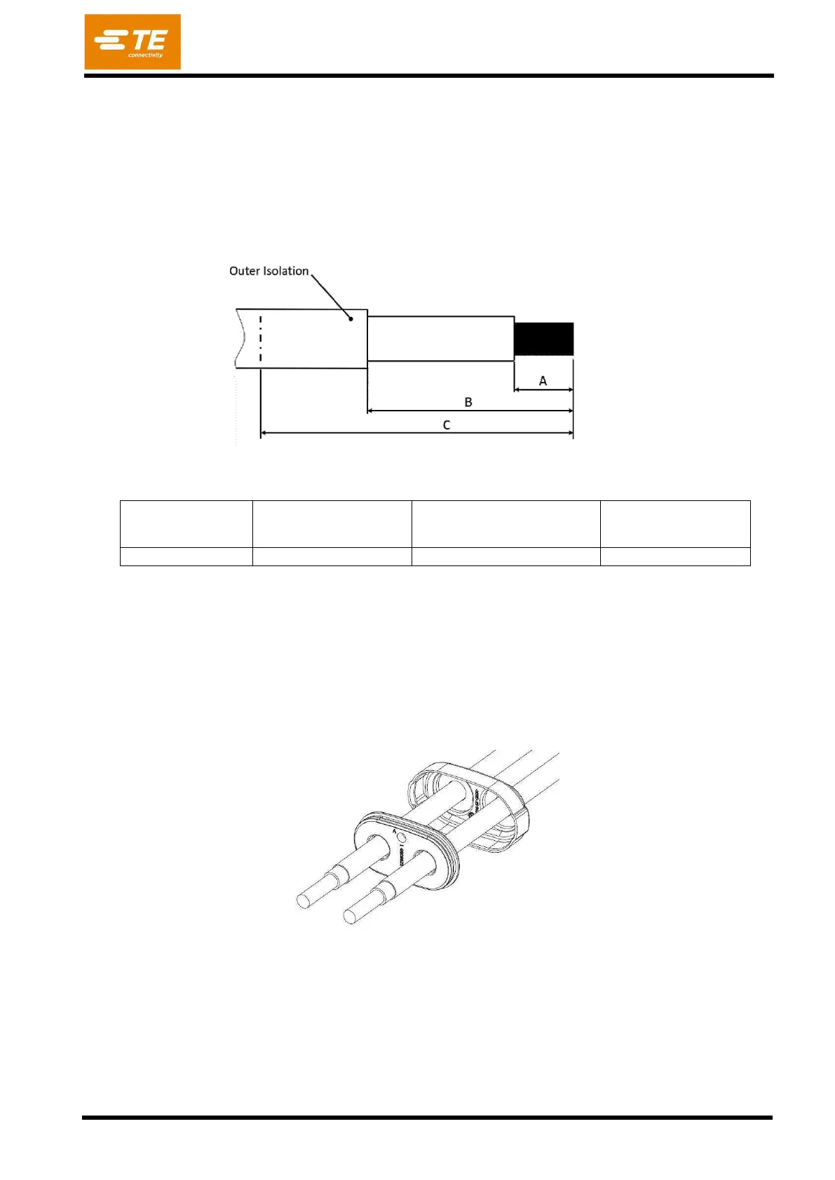
The COVER CABLE SEAL DC [Pos. 10] and FAMILY SEAL DC [Pos. 11] must be pushed over the
DC-HV-wires (figure 35)
Alternative it is also possible to process with folded shielding braid and OUTER FERRULE [Pos. 16]
according step 5b described in “Processing OUTER FERRULE [Pos.16]”.