114-94438 REV C1
Step 13
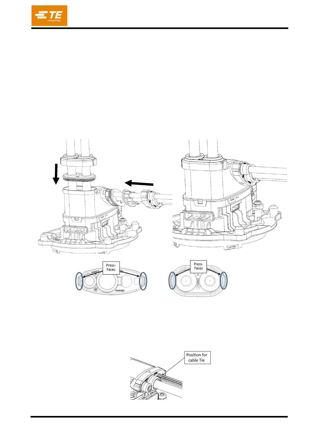
Move the STRAIN RELIEF AC [POS. 8] together with FAMILY SEAL AC [POS. 7] into their position in
the CABLE EXIT [POS. 6]. Ensure that all wires (AC-Multicore, PE-Single wire, LV-wires) are well
positioned in the FAMILY SEAL, so that the seal lips are placed on the outer isolation of the cables
Ensure that the mark from Step 2 is on the same Level to the End of the CABLE EXIT [Pos. 6].
Push the COVER CABLE SEAL AC [POS. 9] over it and snap it on the CABLE EXIT [Pos. 6]. Ensure
that both hooks are properly engaged. Typical press-on-force = 250N; max. press-on-force = 500N.
Move the FAMILY SEAL DC [Pos.11] into the CABLE EXIT [Pos. 6] and snap the COVER CABLE
SEAL DC [Pos. 10] over CABLE EXIT COVER [Pos. 6]. Ensure that both hooks are properly engaged.
Typical press-on-force = 250N; max. press-on-force = 500N.
Place a cable tie (proposed dimensions 2,5mm wide, material to be heat stabilized and suitable for
automotive use) around the single wire signal cables and the bridge next to the Cover Cable Seal
[Pos. 9] and pull tight (Positioning see figure 47).